
Digging laneway aerating and dust removing system arrangement method

A technology of dust removal system and layout method, which is applied to ventilation, dustproof and safety devices in mines/tunnels, can solve problems such as poor dust removal effect and difficulty in capturing dust, and achieve low water consumption, reasonable ventilation layout, and dust removal effect. Good results

Inactive Publication Date: 2008-04-30
TANGSHAN KAILUAN GUANGHUI EQUIP MFGCO
View PDF0 Cites 33 Cited by
  • Summary
  • Abstract
  • Description
  • Claims
  • Application Information

AI Technical Summary

Problems solved by technology

[0003] The present invention aims at many deficiencies in the prior art, such as frequent movement and installation of dust removal devices, repeated suspension of negative pressure air cylinders, difficulty in catching dust, and poor dust removal effect, and provides a ventilation and dust removal method using long pressure and short pumping, which has a good dust removal effect, Arrangement method of tunnel ventilation and dust removal system with simple process

Method used


Image

  • Digging laneway aerating and dust removing system arrangement method
  • Digging laneway aerating and dust removing system arrangement method
  • Digging laneway aerating and dust removing system arrangement method

Examples


Embodiment 1

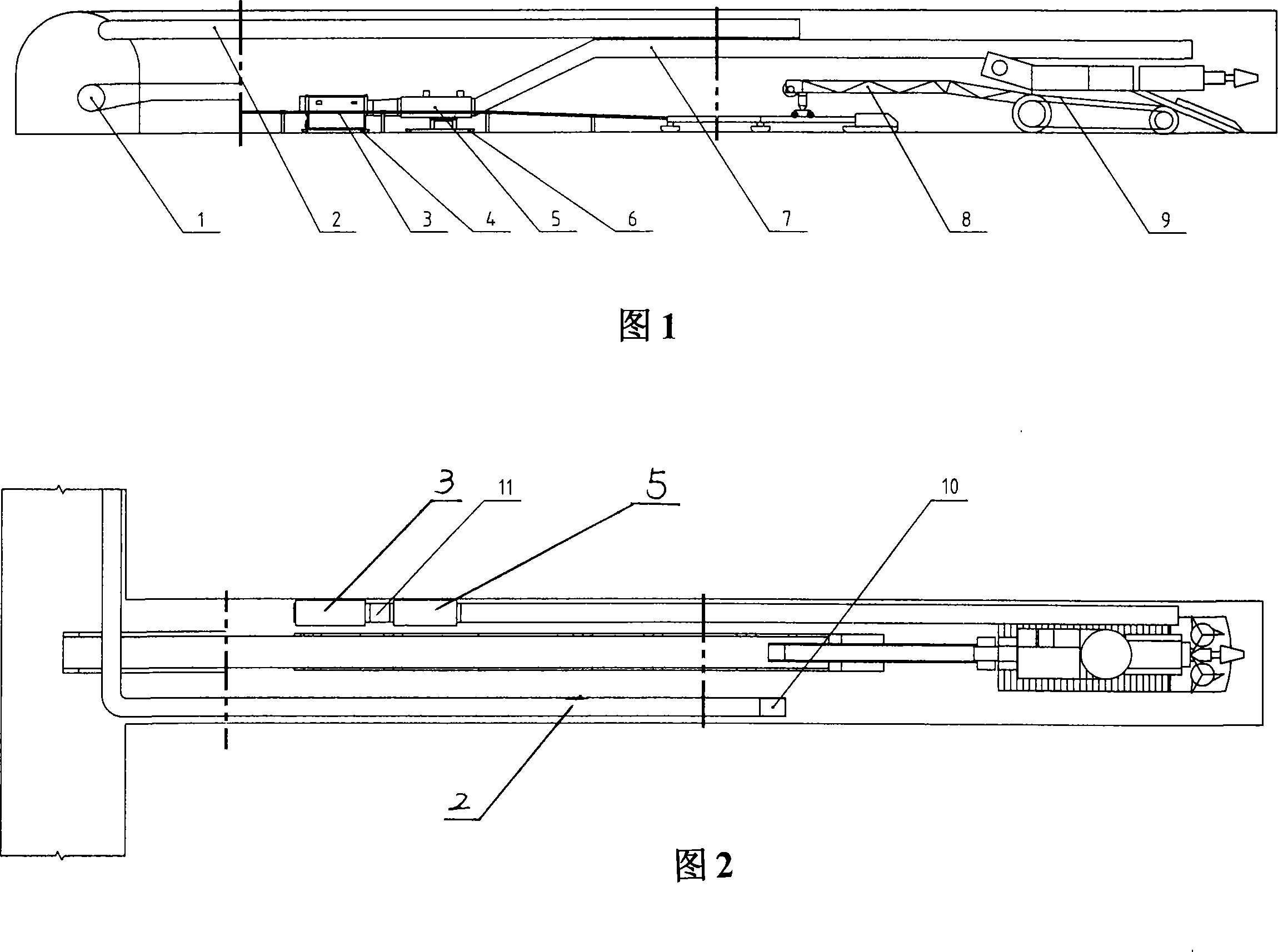
[0019] Embodiment 1, the basic machine excavation ventilation and dust removal system, it mainly consists of a belt conveyor 1, two positive pressure air cylinders 2, 11, a dust collector 3, a dust collector skid 4, a fan 5, a fan skid 6, and a negative pressure air cylinder. Tube 7, belt transfer machine 8, roadheader 9, cyclone 10 and other components. The connection relationship and installation position of each component are shown in the structural diagram 1 and attached drawing 2. The roadheader 9 and the belt transfer device 8 are connected in the form of docking; the transfer device 8 is erected on the belt conveyor 1 . The negative pressure air cylinder 7 is connected with the blower fan 5 by a clamp, and the negative pressure air cylinder 7 is hung on the roadway. The dust remover 3 is erected on the dust remover skid 4. The fan 5 is erected on the fan skid 6, and the fan 5 is connected with the positive pressure air cylinder 11 by a clamp. The positive pressure air...

Embodiment 2

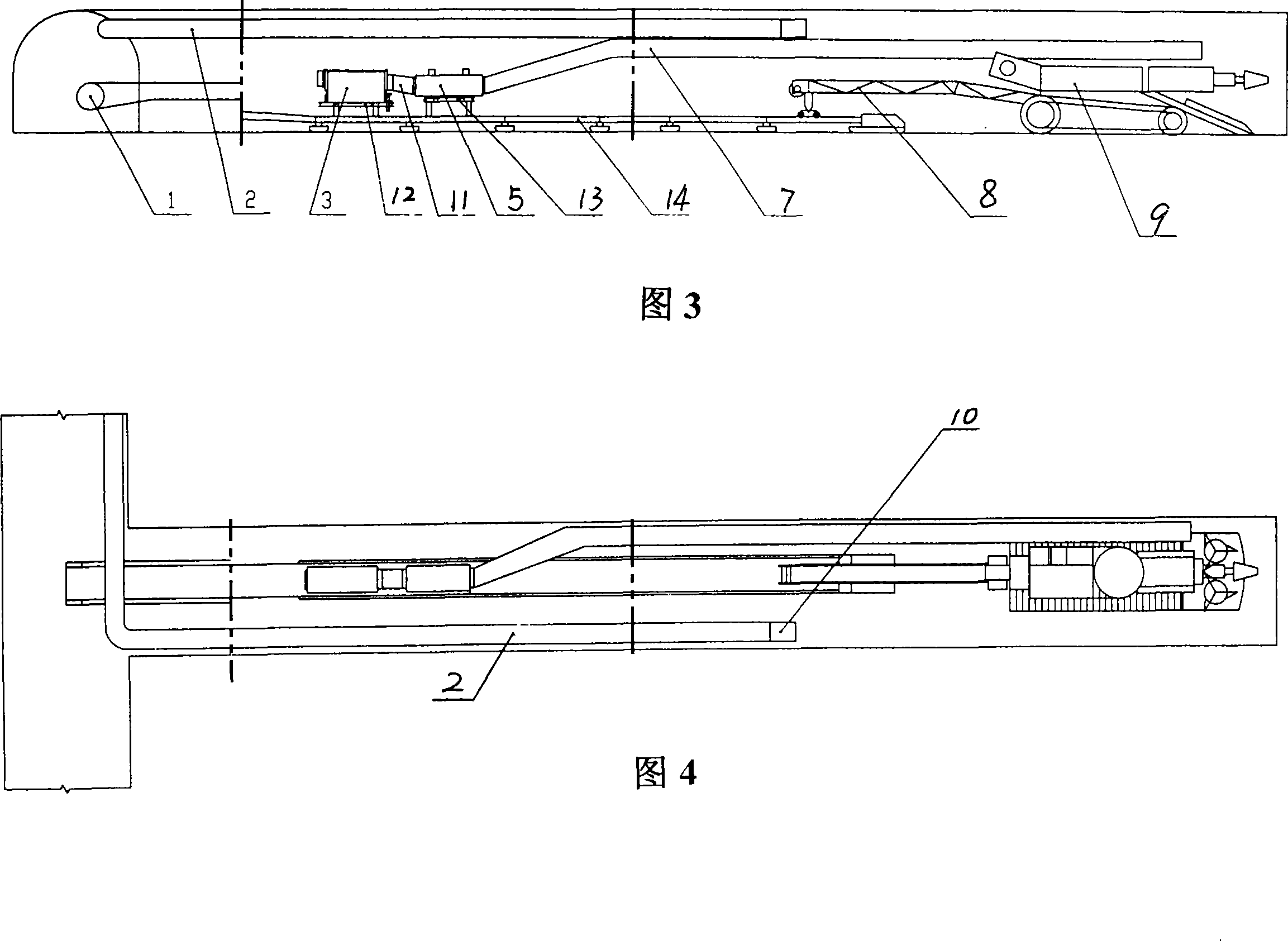
[0021] Embodiment 2, fixed frame belt conveyor tail machine excavation ventilation and dust removal system, it mainly consists of belt conveyor 1, positive pressure air cylinder 2, 11, dust collector 3, blower fan 5, negative pressure air cylinder 7, belt transfer machine 8, tunneling Machine 9, cyclone 10, dust collector support 12, fan support 13, belt conveyor tail 14 and so on. The connection relationship and installation position between the various components are shown in the structural diagram 3 and Figure 4. The roadheader 9 is connected with the belt transfer device 8 in a docking form; the transfer device 8 is erected on the tail 14 of the belt conveyor; 5 is connected by a clamp; the negative pressure air cylinder 7 is hung on the roadway; the dust collector 3 is erected on the dust collector support 12; the fan 5 is erected on the fan support 13; the fan 5 and the positive pressure air cylinder 11 are connected by a clamp; The positive pressure air cylinder 11 and ...

Embodiment 3

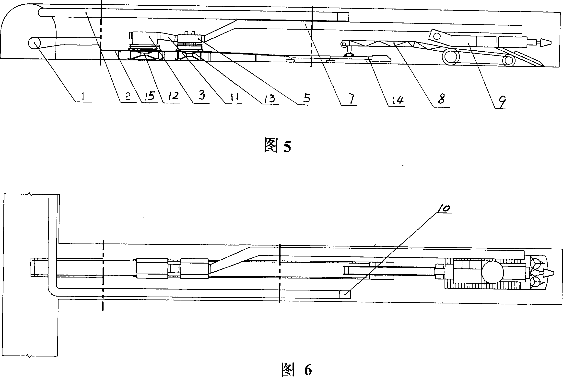
[0024] Embodiment 3: Cross-belt longitudinal beam machine digging ventilation and dust removal system, which mainly consists of belt conveyor 1, positive pressure air cylinder 2, belt longitudinal beam 15, dust collector support 12, dust collector 3, positive pressure air cylinder 11, fan support 13. Fan 5, negative pressure air cylinder 7, belt conveyor tail 14, belt transfer machine 8, roadheader 9, cyclone 10, etc. The connection relationship and installation position between the various components are shown in the structural diagrams 5 and 6. The roadheader 9 and the belt loader 8 are connected in a docking form; the belt loader 8 is erected on the tail 14 of the belt conveyor; 5 is connected by clamps; the negative pressure air cylinder 7 is hung on the roadway; the fan 5 and the dust collector 3 are erected on the fan bracket 13 and the dust collector bracket 12; the dust collector bracket 12 and the fan bracket 13 are straddled on the belt longitudinal beam 15 Above; th...


PUM


Abstract

The invention provides an arrangement method of a ventilating and dust-removing system for the excavation tunnel, and includes a boring machine, a belt feeding machine, a belt transshipment device, a dust-removing device, and a ventilating device. The boring machine is connected with the belt transshipment. The transshipment device is set on the belt feeding machine, and the negative pressure wind cylinder of the ventilating device is hung on the tunnel and connected with a fan in a hooping method. Two positive pressure wind cylinders are arranged on the ventilating device, one positive pressure wind cylinder is connected with a fan and a dust catcher in the hooping method; the other positive pressure wind cylinder is connected with a cyclone in the hooping method and is hung on the tunnel. The dust catcher of the dust-removing device is set up on a dust catcher supporting device. The dust-removing device is arranged on a position 20 to 40 meters behind the boring machine, and the negative pressure wind cylinder is connected at a position 3 to 5 meters apart from and opposing the drivage face, fresh air is pressed in by the positive pressure wind cylinder, and the outlet is 15 to 35 apart from and opposing the drivage face. The ventilation arrangement of the method is rational and safe, the movement is convenient, the operation is simple, the dust removing effect is good, the water consumption is low, and the cost is low.

Description

Technical field: [0001] The invention relates to a method for arranging a ventilation and dust removal system, in particular to a method for arranging a ventilation and dust removal system for an excavation roadway which is suitable for excavation of mine roadways and tunnels of highways, railways and subways and where dust sources are concentrated. Background technique: [0002] Dust is one of the main natural disasters in mine excavation roadways, highways, railways, and subway tunnels. With the continuous improvement of the level of mechanization, the amount of dust generated is increasing. According to actual measurements, the dust concentration during machine excavation is as high as 1000- 3000mg / m 3 , and the degree of dispersion is high, among which respirable dust with a particle size of less than 7 μm accounts for more than 85%, which seriously threatens the safety and health of on-site workers. At present, there are many types of dust removal equipment in China, b...

Claims


Application Information

Patent Timeline
Patent Type & Authority Applications(China)
IPC IPC(8): E21F5/20E21F1/00
Inventor 赵耀山
Owner TANGSHAN KAILUAN GUANGHUI EQUIP MFGCO
Learn More