
Volume controlled rotary compressor air-breathing device

A rotary compressor and capacity control technology, which is applied to rotary piston machinery, rotary piston pumps, rotary piston/swing piston pump components, etc., can solve the problem of reduced refrigeration capacity, complex processing technology, high working noise, etc. problem, to achieve the effect of low working noise, simple processing and assembly process, and low production cost

Inactive Publication Date: 2008-04-30
GUANGDONG MEIZHI COMPRESSOR
View PDF0 Cites 11 Cited by
  • Summary
  • Abstract
  • Description
  • Claims
  • Application Information

AI Technical Summary

Problems solved by technology

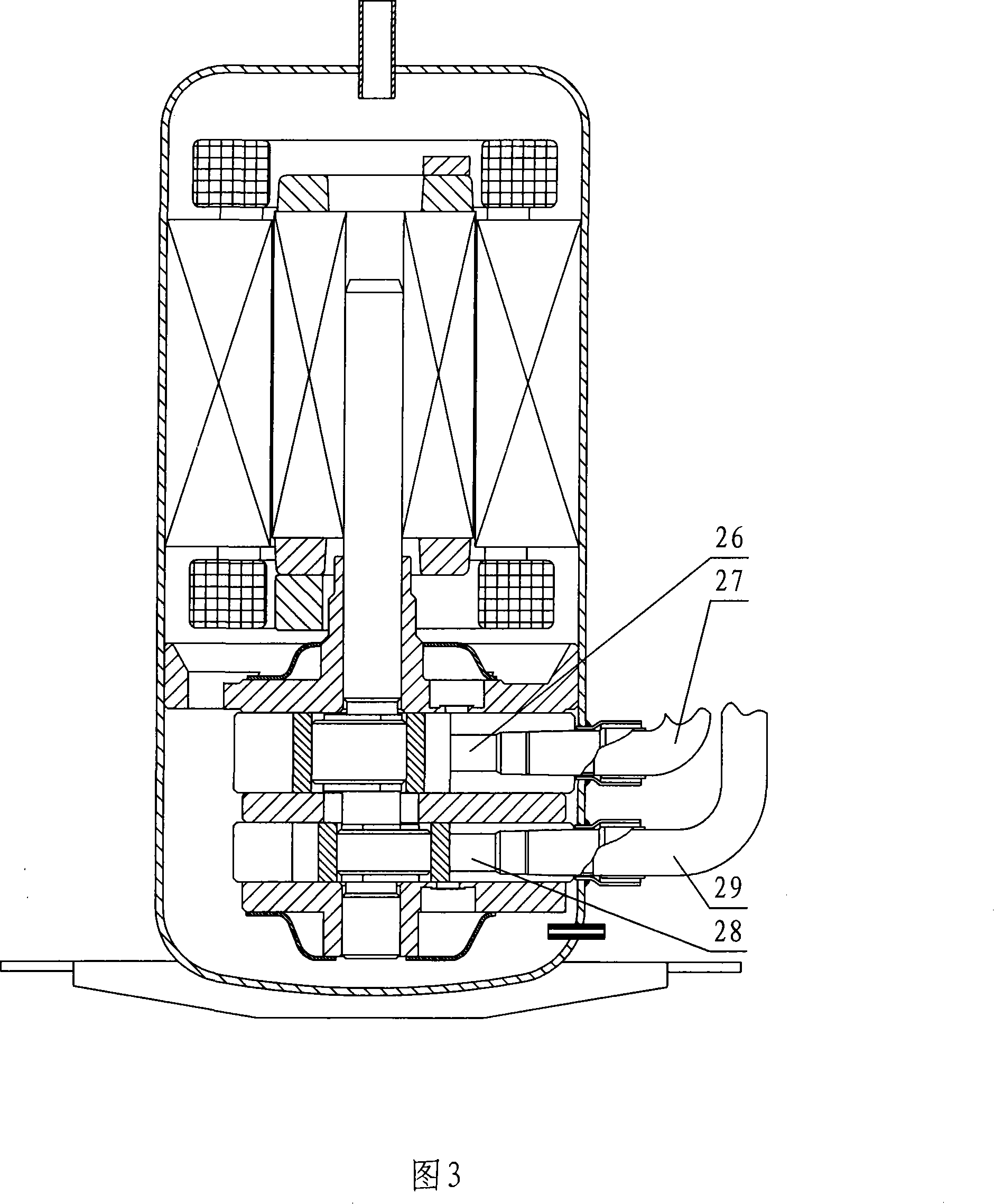
Figure 3 shows a sectional view of a two-cylinder rotary compressor with double suction pipes. The upper cylinder 12 sucks air through the upper suction pipe 27 and the upper suction hole 26, and the lower cylinder 13 passes through the lower suction pipe 29 and the lower suction hole. 28 suction, the two cylinders are independent suction, the production cost is high, the processing technology is complicated, and the working noise is relatively high
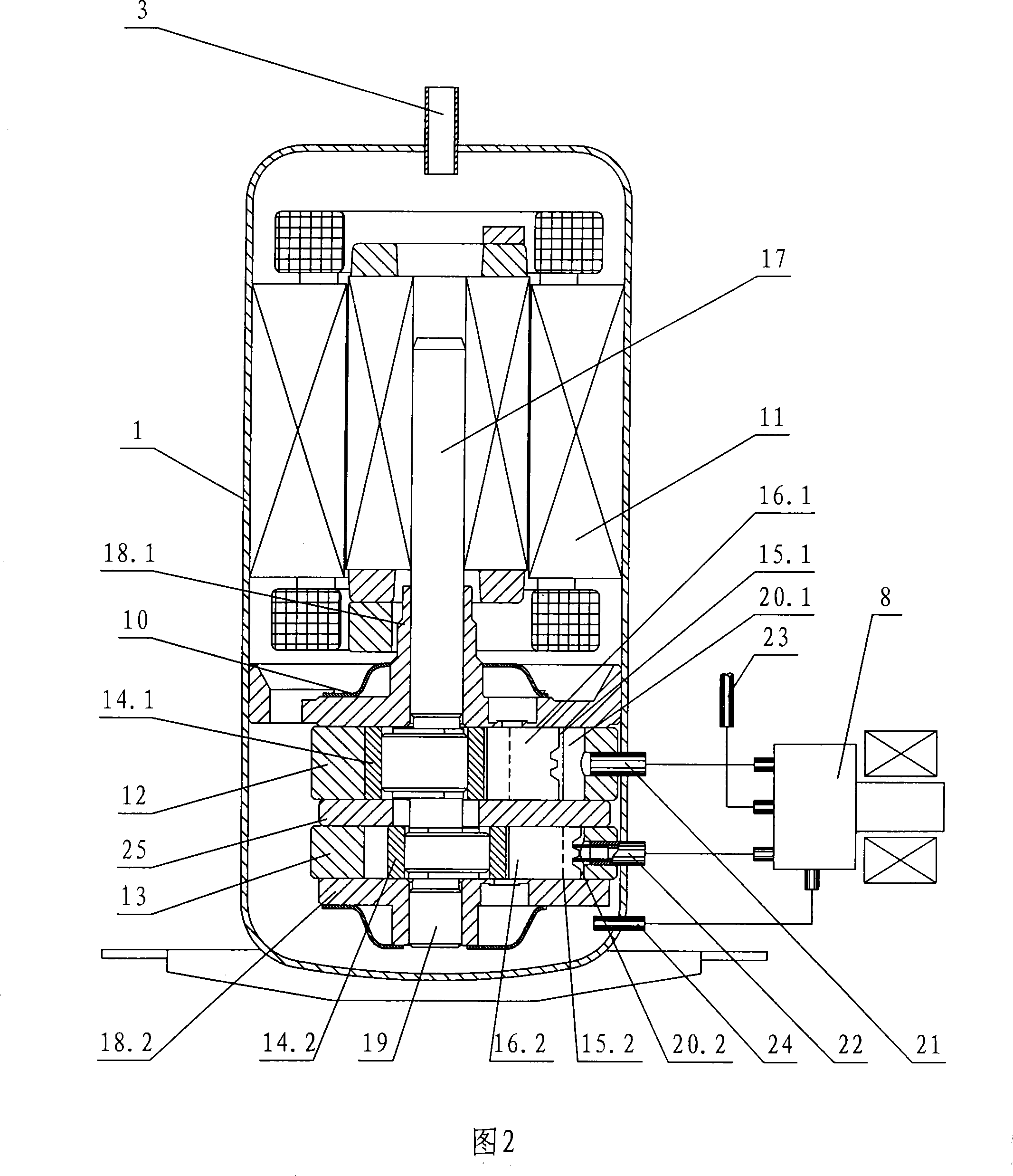
[0004] However, new research has found that when there are many two-cylinder rotary compressors with capacity control functions, the compression function of one cylinder will be stopped, and the displacement of the compressor, that is, the refrigeration capacity will be reduced to 30-70%. use

Method used


Image

  • Volume controlled rotary compressor air-breathing device
  • Volume controlled rotary compressor air-breathing device
  • Volume controlled rotary compressor air-breathing device

Examples


no. 1 example

[0041] Referring to Fig. 4, the first suction pipe 37 in the suction device of the capacity control rotary compressor is connected to a cylinder, which can be either an upper cylinder or a lower cylinder, and the other cylinder is connected to the through hole of the partition plate Connect to air intake.

[0042] Referring to Figure 5, the first suction pipe 37 is connected to the upper cylinder, a part of the gas enters the upper cylinder through the upper suction hole 26, and the other part of the gas passes through the axial hole 31 of the upper cylinder, the partition through hole 30 on the partition and the lower cylinder in sequence. The upper first lower suction hole 28' enters the lower cylinder.

[0043] Referring to Figures 6-7, for a capacity-controlled rotary compressor, when the compressor operates at 100% capacity, both cylinders suck and compress. As mentioned earlier, a part of the gas enters the upper cylinder through the upper suction hole. Another part of ga...

no. 2 example

[0053] Referring to Fig. 19-Fig. 20, the second suction pipe 38 is first connected with the partition 25, and then connects with the upper and lower suction holes 36, the upper suction hole 26 or the lower suction hole 28 respectively through the partition board suction hole 36 and the lower suction hole 28 provided on the partition board. The two cylinders are connected. The gas under this structure has the shortest distance to reach the two cylinders, and both the two-stage variable capacity compressor and the three-stage variable capacity compressor can be used.

[0054] Referring to Fig. 21-Fig. 22, in order to reduce the resistance of the gas in the flow process, wedge-shaped cutouts 34 or a combination of wedge-shaped cutouts 34 and cylinder axial holes 35 are respectively set on the path from the diaphragm suction hole 36 to the upper and lower cylinders. The angle α of the notch is between 30° and 90°, including 30° and 90°, wherein the wedge-shaped notch 34 and the ax...


PUM


Abstract

The invention provides a suction device of a capacity controlling rotary compressor. The suction device includes a motor, an upper cylinder and a lower cylinder which are arranged in the shell body of the compressor, a clapboard arranged between the cylinders, pistons arranged in the cylinders, a sliding vane arranged in a cylinder sliding vane slot, an eccentric crankshaft for driving the piston to operate, a bearing for supporting the eccentric crankshaft, and a capacity valve for controlling the capacity. The two cylinders share a same suction pipe. The suction pipe is communicated with a cylinder of normal working state in a two-step varactor or with a higher-displacement cylinder in a three-step varactor, or the suction pipe is communicated with the clapboard, the clapboard is respectively communicated with the upper and the lower cylinders. The upper cylinder is directly communicated with a first suction pipe; the lower cylinder is communicated with the first suction pipe through a lower suction hole arranged on the lower cylinder, a clapboard through hole arranged on the clapboard, and a cylinder axial communicating hole arranged on the upper cylinder. The invention has the advantages that the manufacturing cost is low, the noise is low, the libration is slight, and the process and the assembling techniques are simple.

Description

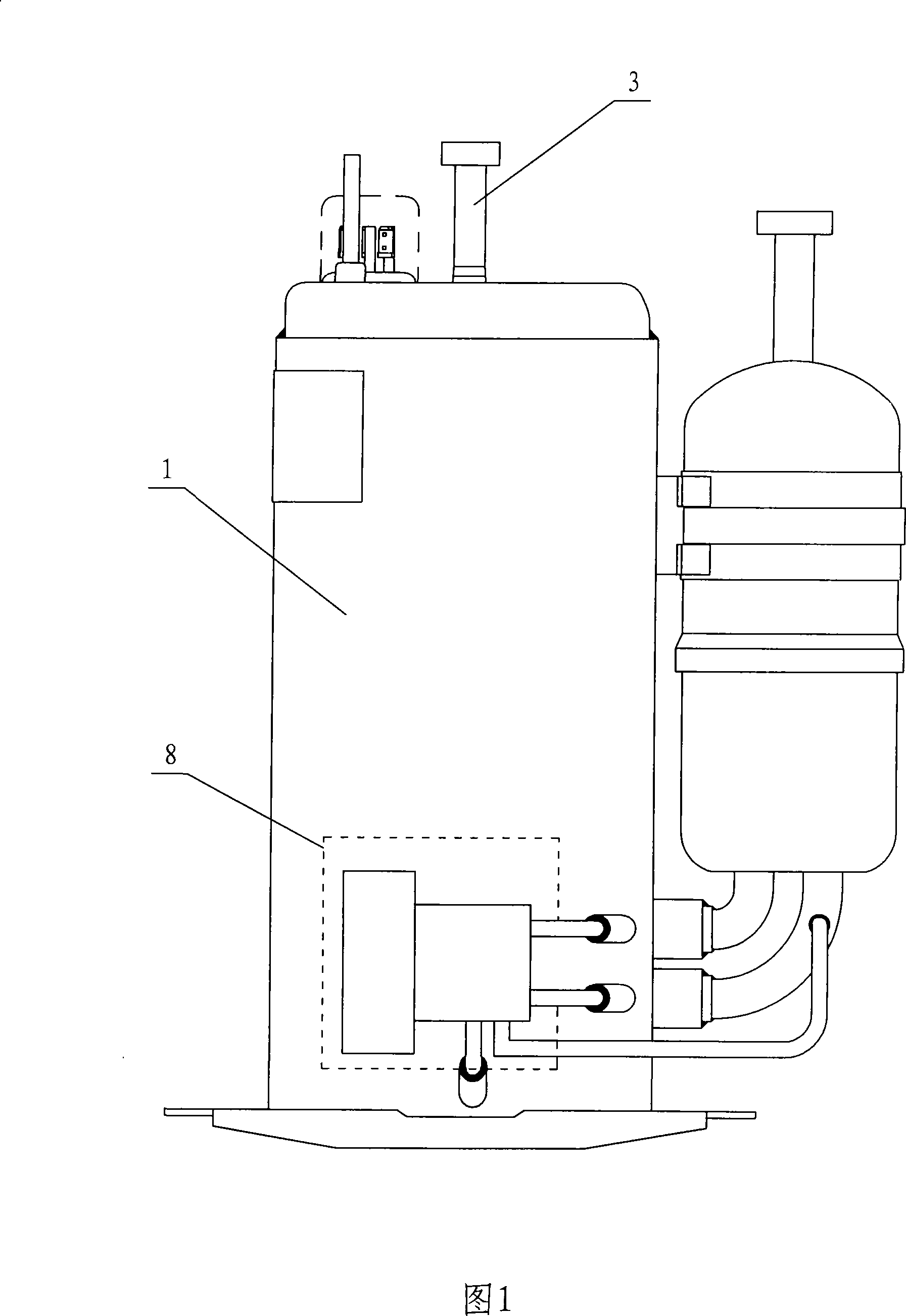
technical field [0001] The invention relates to a capacity control rotary compressor, in particular to a suction device of the capacity control rotary compressor. Background technique [0002] In order to control the capacity of the rotary compressor, on the basis of the frequency conversion technology that has been commercialized at present, the research on the capacity control of the rotary compressor that changes the displacement of the compressor in the fixed-speed two-cylinder rotary compressor is increasingly advanced. . The twin-cylinder rotary compressor without the capacity control function has become a known technology on USP (United States Patent) before 1960, and a communication hole is provided on the dividing plate separating the two cylinders. In this patent, a suction circuit is designed to communicate with the lower cylinder, and the suction gas is distributed to the upper cylinder through the communication hole. The two-cylinder rotary compressor without ...

Claims


Application Information

Patent Timeline
IPC IPC(8): F04C29/12F04C23/00
CPCF04C28/24F04C18/3564F04C23/008F04C23/001
Inventor 邵海波
Owner GUANGDONG MEIZHI COMPRESSOR
Learn More