
Water-bath type liquefied natural gas evaporator

A liquefied natural gas, water bath technology, applied in the direction of pressure vessels, fixed-capacity gas storage tanks, container discharge methods, etc., can solve the problems of small vaporization, incoherent gas supply, large volume, etc., to avoid pipeline blockage, Easy installation and reduced volume

Inactive Publication Date: 2008-04-30
ZHANGJIAGANG FURUI SPECIAL EQUIP CO LTD
View PDF0 Cites 11 Cited by
  • Summary
  • Abstract
  • Description
  • Claims
  • Application Information

AI Technical Summary

Problems solved by technology

The disadvantages of this kind of carburetor are: large volume, inconvenient installation of the carburetor; small vaporization volume, inconsistent air supply, which cannot meet the needs of the engine

Method used


Image

  • Water-bath type liquefied natural gas evaporator

Examples


Embodiment Construction

[0010] The specific embodiments of the present invention will be described in detail below with reference to the accompanying drawings.

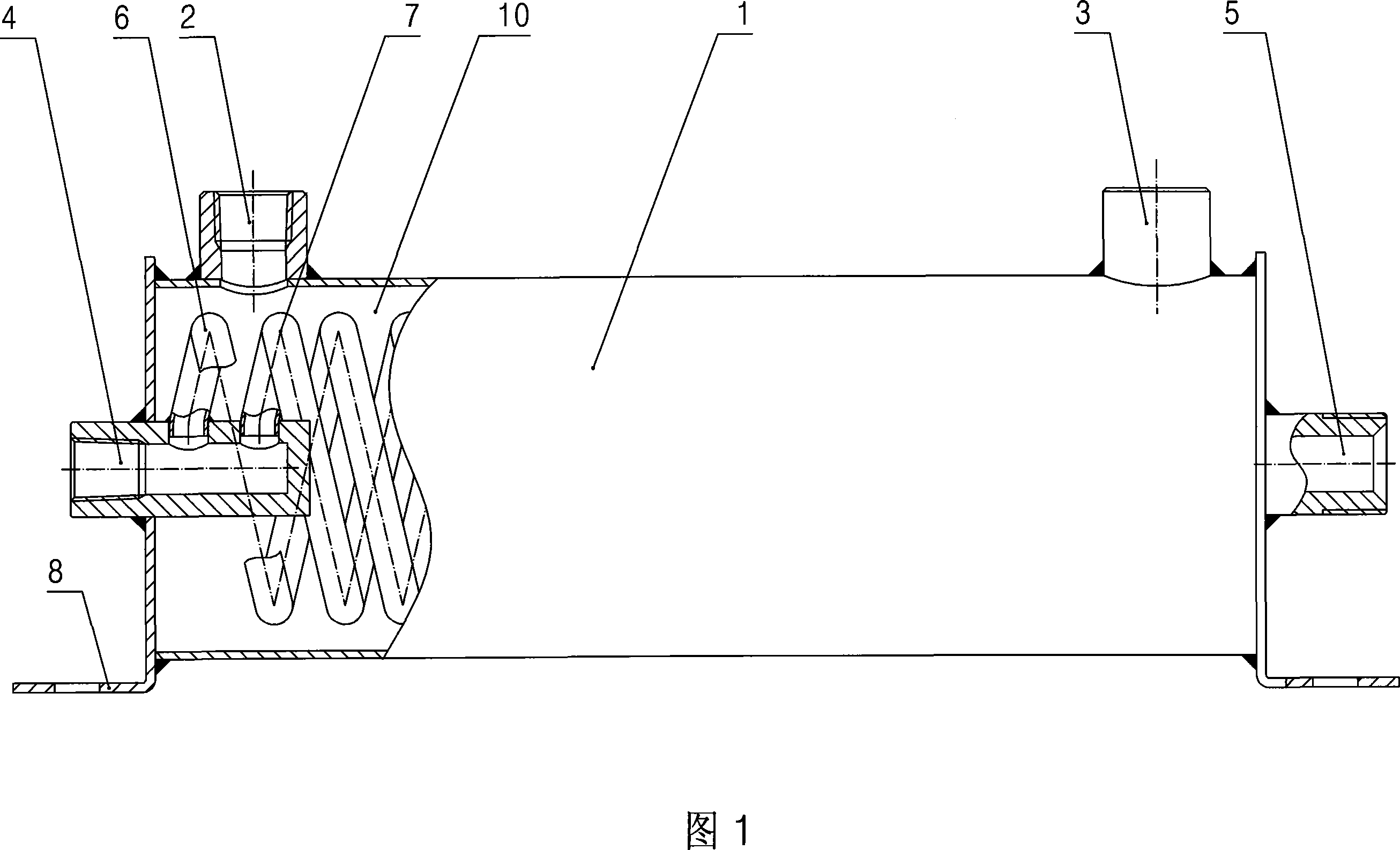
[0011] As shown in Figure 1, the water bath type liquefied natural gas vaporizer of the present invention includes: a water bath type cylinder 1, a closed heat exchange cavity 10 is built in the water bath type cylinder 1, and the water bath type cylinder 1 is provided with a The inlet and outlet ports 2 and 3 of the heat chamber 10 communicate with each other. The heat exchange chamber 10 is provided with two spiral heat exchange tubes 6 and 7 that are wound together. The two ends of the heat exchange tube 6 are connected to each other. The vaporized natural gas inlet 4 and the natural gas outlet 5 at the two ends of the water bath cylinder 1 are connected, and the two ends of the heat exchange tube 7 are respectively connected with the vaporized natural gas inlet 4 and the natural gas outlet 5 that pass through the two ends of the water bath c...


PUM


Abstract

The invention discloses a water bath type liquefied natural gas carburetor which has convenient installation and good effect of continuously supplying air to the engine. The carburetor includes a water bath type cylinder body which is internally provided with a heat exchange cavity, wherein, the water bath type cylinder body is provided with a water inlet and a water outlet, which are communicated with the heat exchange cavity. The heat exchange cavity is internally provided with two spiral heat exchange tubes which are entwisted together. Both ends of each heat exchange tube are respectively communicated with a liquefied natural gas inlet and a natural gas outlet, and the liquefied natural gas inlet and the natural gas outlet are respectively arranged on both ends of the water bath type cylinder body. The invention is used for gasifying the liquefied natural gas to normal natural gas and supplying gas for the engine.

Description

Technical field [0001] The invention relates to a vaporizer for water-bath type liquefied natural gas. Background technique [0002] At present, countries around the world are actively exploring the use of natural gas as vehicle fuel to reduce the pollution of vehicle exhaust to the atmosphere and protect the earth's ecological environment. There are roughly two ways to use natural gas as vehicle fuel: The first way is to store the compressed natural gas in a gas cylinder, and then use the compressed natural gas in the gas cylinder as a gas source, and supply it directly after being decompressed by a pressure reducing device. For the engine, this method is relatively simple and easy to implement, but the air storage per unit volume is small, which makes a single stroke shorter and can only be used for short-distance driving; moreover, due to the high pressure in the cylinder, It brings safety hazards to the transportation and use of gas cylinders; another way is to store LNG in t...

Claims


Application Information

Patent Timeline
Patent Type & Authority Applications(China)
IPC IPC(8): F17C7/04
Inventor 刘永平
Owner ZHANGJIAGANG FURUI SPECIAL EQUIP CO LTD
Learn More