Method for detecting abnormity of flux control valve of air-jet loom
A technology of flow control valve and air-jet loom, which is applied in the direction of looms, weaving auxiliary equipment, textiles, etc., can solve problems such as inability to detect, and quality defects in weaving completion, so as to prevent quality deterioration, improve reliability, The effect of improving reliability
Inactive Publication Date: 2008-05-07
TOYOTA IND CORP
View PDF0 Cites 4 Cited by
- Summary
- Abstract
- Description
- Claims
- Application Information
AI Technical Summary
Problems solved by technology
[0005] However, in the technique disclosed in Patent Document 1, there is a problem that detection cannot be performed when there is malfunction in the throttle device 10.
In the case of failure due to poor rotation or poor contact of the motor 25 of the throttling device 10, the throttling of the flow rate cannot be performed by the throttling device 10, but the loom can be operated as usual because the abnormality cannot be detected in advance. There is a possibility of major defects in the quality of the weaving finish
Method used
View moreImage
Smart ImageViewing Examples

Examples
no. 2 approach
[0053] Next, a second embodiment of the present invention will be described based on FIG. 1 .
[0054] In this embodiment, the kind of the weft detection device in the first embodiment is changed.
[0055] Therefore, here, for the convenience of description, some symbols used in the previous description are shared, the description of the common parts is omitted, and only the changes are described.
Login to view more PUM
 Abstract
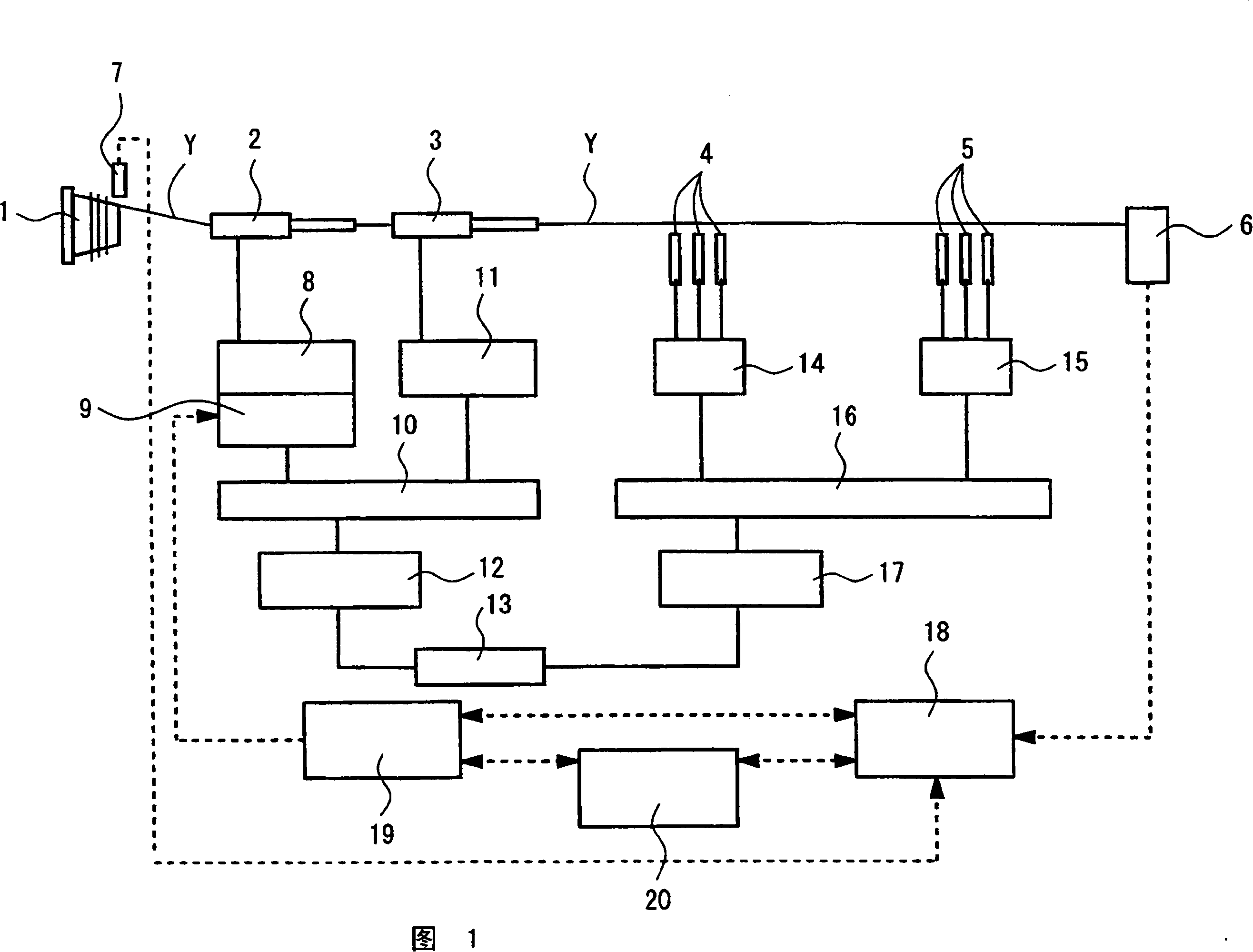
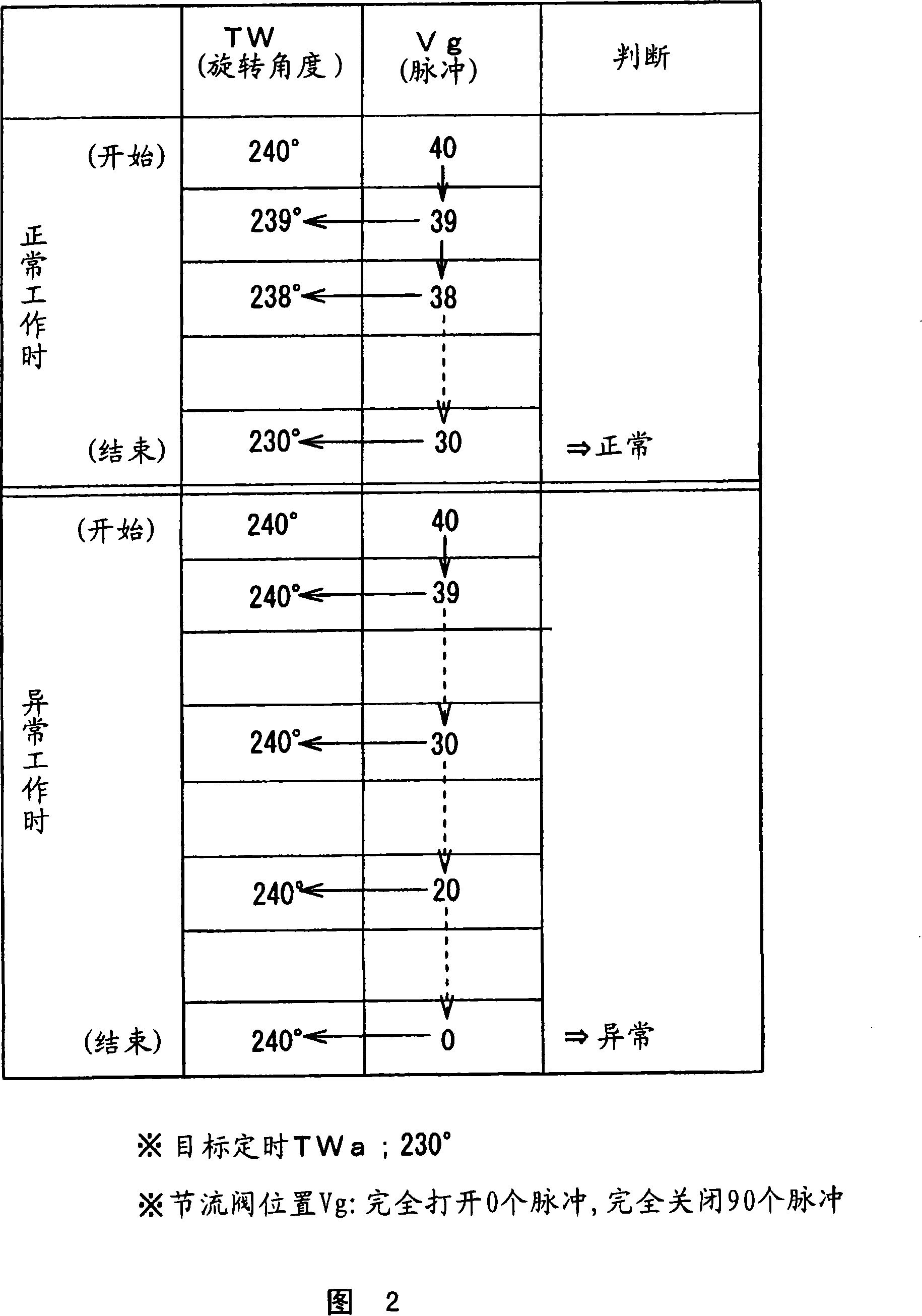
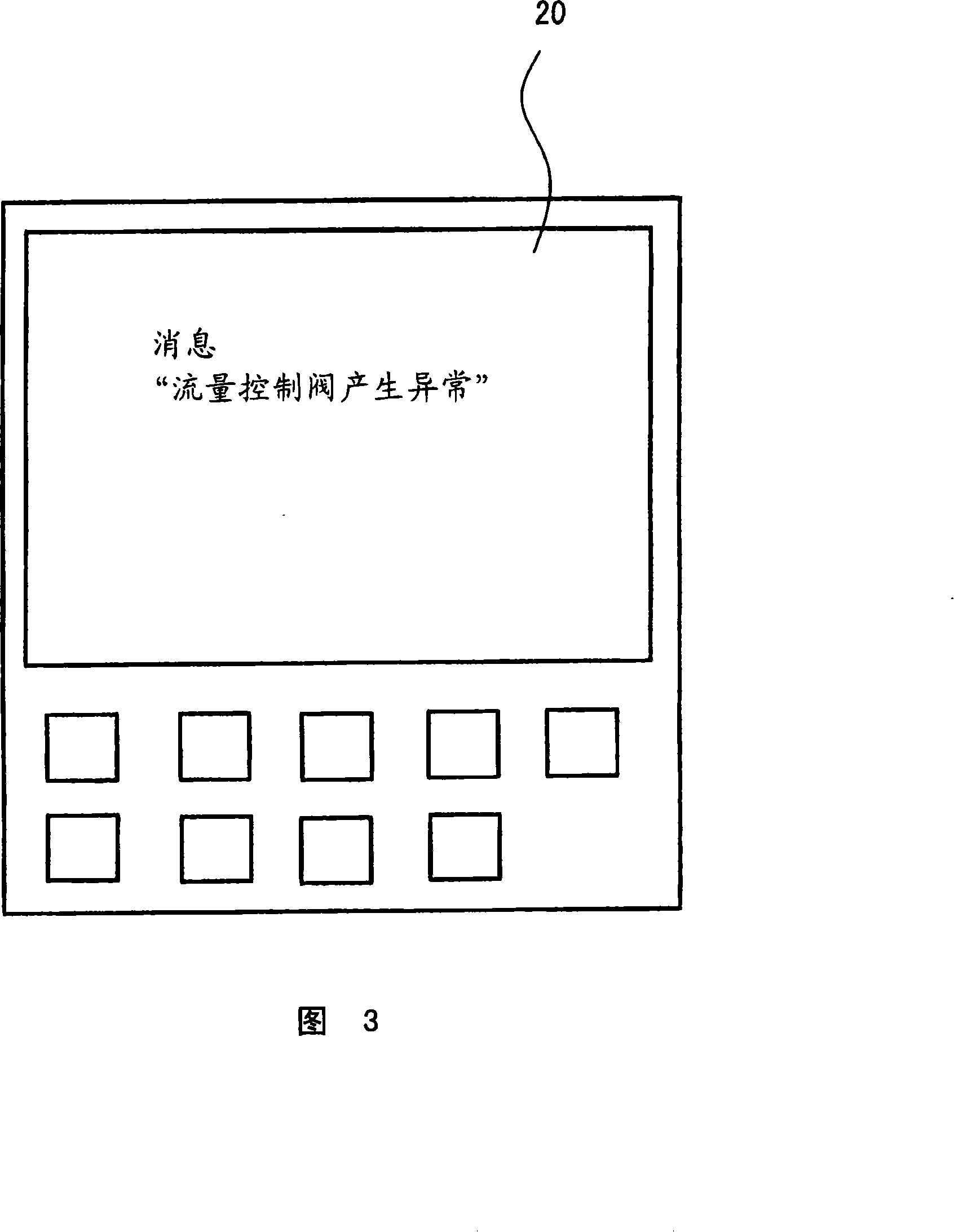
The invention provides an abnormity detecting method of a flow control valve of a jet looms, which can detect the work abnormity of the flow control valve of the looms ahead of time and seek to improve the reliability of the looms. The invention is an abnormity detecting method of a flow control valve of a jet looms and the jet looms is provided with a feeler (6) reaching the time TW when detecting a latitude Y and an electric type flow control valve (9) connected with a series nozzle and adjusting the supply air flow of the series nozzle, capable of using the motor drive of the electric type flow control valve (9) to control the reach time TW of the latitude Y. Wherein, the change of the reach time TW of the latitude Y before and after the drive of the motor of the electric type flow control valve (9) is contrasted, thereby detecting the work abnormity of the electric type flow control valve (9) to produce the warming signal.
Description
technical field [0001] The present invention relates to an abnormality detection method of a flow control valve that adjusts the flow rate of supply air for weft thread input of an air-jet loom. Background technique [0002] In the prior art disclosed in Patent Document 1, a main nozzle 4 is provided on a slay 12, a guide path is formed in front of the main nozzle 4, a relay nozzle 6 is provided in the middle, and a guide path is provided at the end of the guide path. A detector 15 that detects the arrival of the weft thread 1 . Furthermore, an auxiliary nozzle 5 is provided adjacent to the main nozzle 4 . [0003] The main nozzle 4 and the auxiliary nozzle 5 are connected to a compressed air source 7, and a shutoff valve 9 and a throttling device 10 are arranged in the middle. The throttling device 10 has a rotary throttling element 24 and a motor 25 , and by rotating the rotary throttling element 24 by the motor 25 , the passing flow rate can be adjusted. [0004] The w...
Claims
Login to view more Application Information
Patent Timeline
 Patent Type & Authority Applications(China)
IPC IPC(8): D03D47/30D03J1/00
Inventor 牧野洋一
Owner TOYOTA IND CORP
- R&D Engineer
- R&D Manager
- IP Professional
Why Eureka
- Industry Leading Data Capabilities
- Powerful AI technology
- Patent DNA Extraction
Try Eureka
Browse by: Latest US Patents, China's latest patents, Technical Efficacy Thesaurus, Application Domain, Technology Topic.
© 2024 PatSnap. All rights reserved.Legal|Privacy policy|Modern Slavery Act Transparency Statement|Sitemap