Fly-shuttle loom harness frame position limiter

A technology of limiting device and heald frame, which is applied in textile, heald, textile and papermaking, etc., can solve the problems of inability to reduce the distance between front and rear healds, unreasonable weaving process, increase in distance, etc. Reduce primary friction, reduce friction effect

Inactive Publication Date: 2008-05-07
丁宏利
View PDF0 Cites 5 Cited by
  • Summary
  • Abstract
  • Description
  • Claims
  • Application Information

AI Technical Summary

Problems solved by technology

But there are following problems in loom shedding weaving process: at first be that the hanging heald place of stepping heald bar of shuttle loom is to do arc swing, like this, the heald frame that is connected with stepping heald bar by hanging heald hook will move up and down. Shaking back and forth causes the warp yarns to rub against the healds, causing the warp yarns to break. Secondly, due to the existence of the heald pulley, the distance between the front and rear heald frames is doubled. In the middle, the height of the rear heddle must be increased, that is, the opening stroke of the rear heddle is greater than the opening stroke of the front heddle, and the deformation of the warp yarn is almost proportional to the square of the shed size, so that the tension of the rear heddle warp yarn is greatly increased after deformation, and it is easy to The main reason for warp yarn breakage in the weaving process is the friction between yarn and yarn, yarn and weaving machine parts such as heddles and unreasonable weaving technology.
At present, weaving factories usually install the discarded shuttle boards at both ends of the heald frame to limit the position of the heald frame and prevent shaking, but it cannot reduce the distance between the front and rear healds, and the use time is too long. After being worn out, the shaking of the heald frame will produce

Method used


Image

  • Fly-shuttle loom harness frame position limiter
  • Fly-shuttle loom harness frame position limiter
  • Fly-shuttle loom harness frame position limiter

Examples


Embodiment Construction

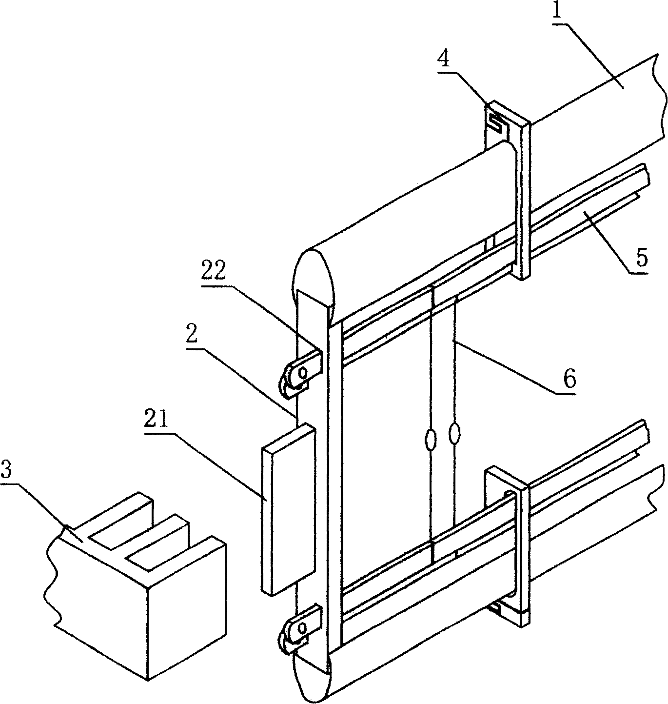
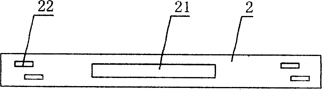
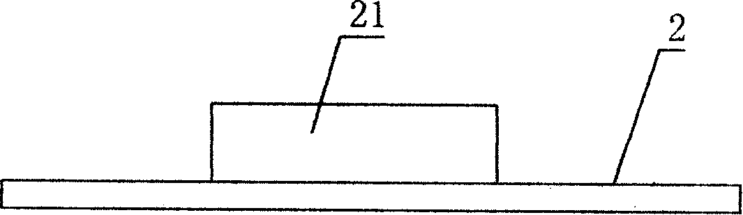
[0021] Such as figure 1 , figure 2 with image 3 As shown, the heald frame limiting device of the shuttle loom includes several rows of heald frames 1 arranged on the loom connected with the heald pulley and the heald rod, which can be two rows of heald frames for weaving plain weave, or can be used for weaving twill Three-column heald frame when weaving, etc. Both ends of the heald frame 1 are respectively provided with a heald head 2, and the heald head 2 is provided with upper and lower rows of perforations 22 for the heald rod 5 with the heddle 6 to pass through the positioning, and the heald rod 5 passes through The heald clamp 4 is fixed on the heald frame 1, and a slider 21 is provided on the heald head 2, and a limit block 3 is respectively provided at both ends of the heald frame 1 on the loom, and a slider 21 is arranged on the limit block 3. Correspondingly, the lifting track that can control the sliding of the slider 21, the sliders 21 respectively provided on ...


PUM


Abstract

The invention discloses a heald frame limit device for shuttle loom, comprising a plurality of heald frames, which is characterized in that: two heald transverse heads are respectively arranged at two ends of a heald frame; an upper row and a lower row of location perforations are arranged on the heald transverse heads of the heald frame for a heald bar to pass through; a plurality of heald yarns pass through the heald bar; the heald bar is fixed on the heald frame via a heald clip; a slider is arranged on each heald transverse head of the heald frame; a limited block is arranged at each end of the heald frame, and a lifting track corresponding to the slider and capability of controlling the sliding of the slider is arranged on the limited block. The invention has the advantages that the shaking of the heald frames in the weaving process is effectively solved and the distance between heald frames is greatly reduced, so that friction between warp and heald yarn or other loom elements in the weaving process is avoided and the end breaking is reduced.

Description

technical field [0001] The invention relates to an auxiliary device on a shuttle loom, in particular to a heald frame limiting device for a shuttle loom which can control the movement of the heald frame on the shuttle loom. Background technique [0002] At present, shuttle looms also occupy a considerable proportion in the weaving of the textile industry. The warp yarn opening of the current shuttle loom relies on the cam to act on the heald pulley to rotate, driving the heald belt to lift up and down, and pulling the heald frame to move up and down so that the warp yarn rises and falls to form a weaving fell for weaving. But there are following problems in loom shedding weaving process: at first be that the hanging heald place of stepping heald bar of shuttle loom is to do arc swing, like this, the heald frame that is connected with stepping heald bar by hanging heald hook will move up and down. Shaking back and forth causes the warp yarns to rub against the healds, causin...

Claims


Application Information

Patent Timeline
Patent Type & Authority Applications(China)
IPC IPC(8): D03J1/00D03C9/06
Inventor 郑德选厉彪苏精东于善勇郑全峰孟凡臣
Owner 丁宏利
Why Eureka
Try Eureka