Centrifugal fan and production method thereof

A centrifugal fan and manufacturing method technology, applied in the direction of mechanical equipment, non-variable pumps, machines/engines, etc., can solve the problems of increased operating procedures, interference between products and molds, increased welding points, etc., to achieve production cost suppression, Realization of productivity and reduction of operation steps

Active Publication Date: 2008-05-07
日本高分子株式会社
View PDF2 Cites 9 Cited by
  • Summary
  • Abstract
  • Description
  • Claims
  • Application Information

AI Technical Summary

Problems solved by technology

[0010] On the other hand, there is a problem that if the shape of the blade member is complicated, the product will interfere with the mold when the mold is released after molding.
[0014] However, if the joining method is used, there is a problem that the blade member and one of the supporting plates must first be trial-assembled, and after forming a semi-finished product by ultrasonic welding, the other supporting plate is further trial-assembled on the semi-finished product. On the other hand, ultrasonic welding is performed again, so that the operation procedures required for welding are increased
[0015] In addition, there is also the following problem: when welding the three parts, i.e., the blade member, the main board, and the shroud, respectively, the blade member and the main board are integrally formed as a semi-finished product in advance, and then the shroud is welded to the shroud by ultrasonic waves. Compared with the case at the end of the blade member in the above-mentioned semi-finished product, the number of welds increases, so it is difficult to ensure the strength and dimensional accuracy of the centrifugal fan as a whole.

Method used


Image

  • Centrifugal fan and production method thereof
  • Centrifugal fan and production method thereof
  • Centrifugal fan and production method thereof

Examples


Embodiment Construction

[0072] Hereinafter, the centrifugal fan of the present invention and its manufacturing method will be described in detail with reference to the drawings.

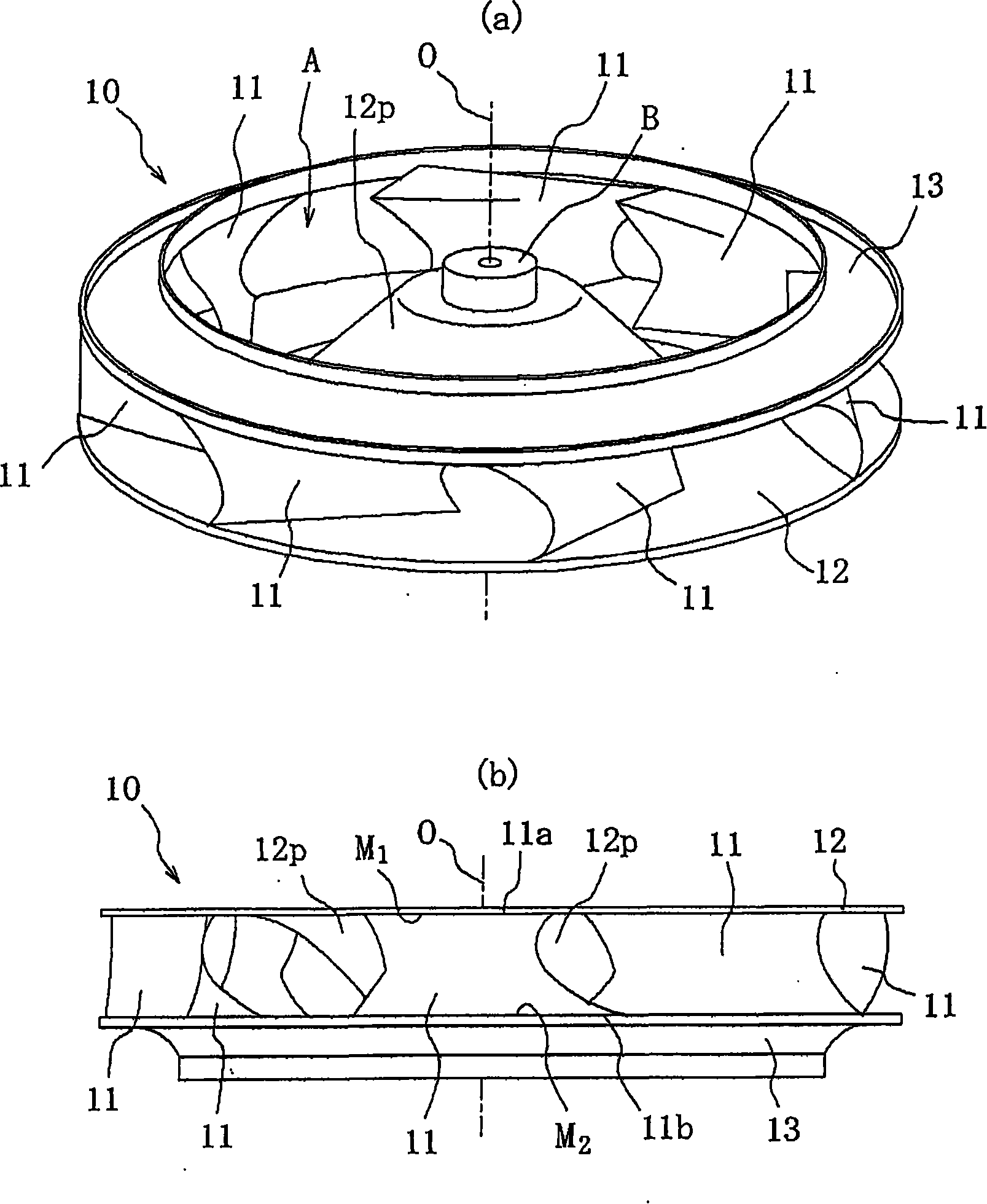
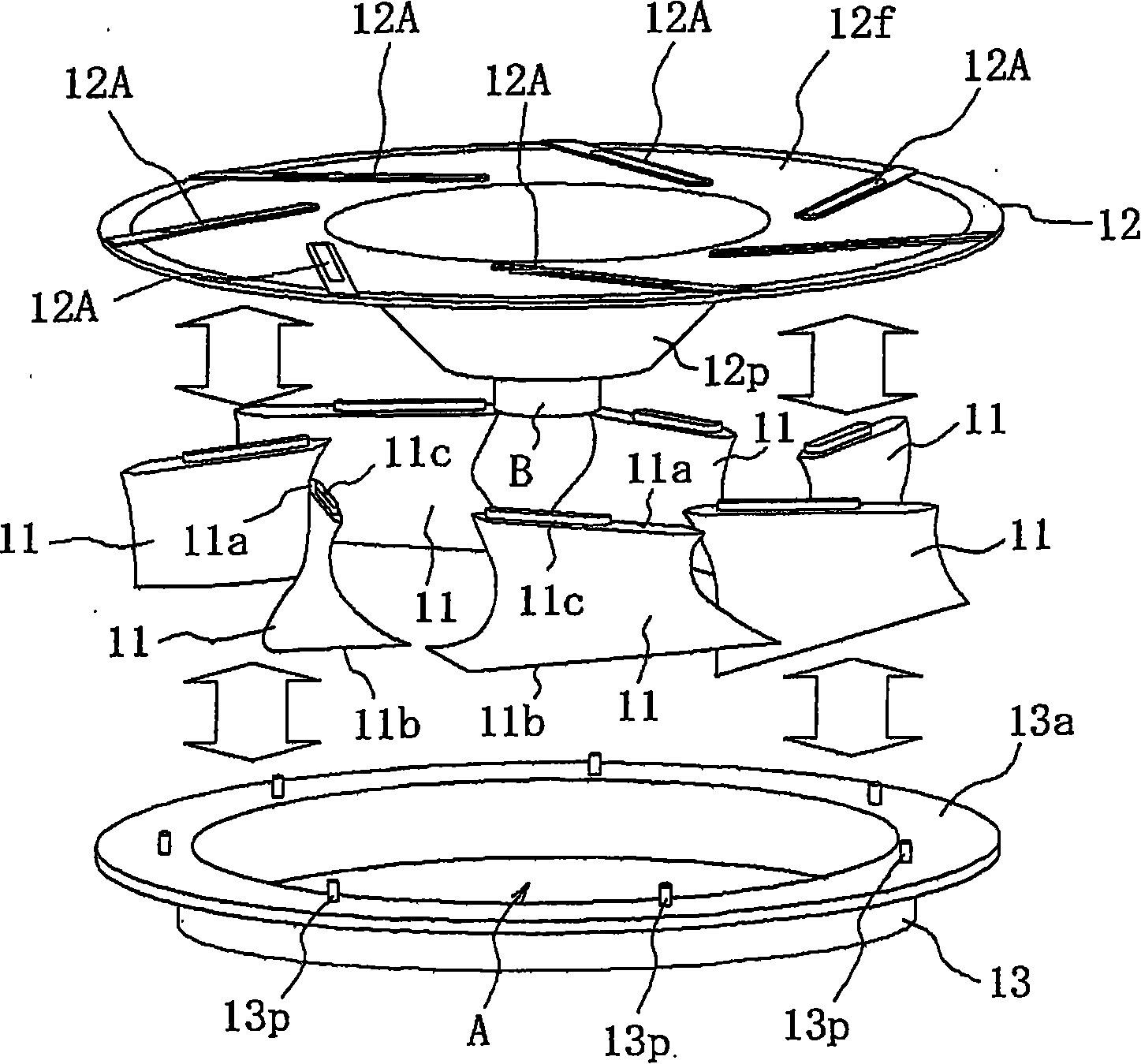
[0073] figure 1 (a) and (b) are a perspective view of the turbo blower 10 as one aspect of the present invention, and a side view of a state in which the aspect is reversed, respectively, figure 2 is true figure 1 (b) is a perspective view of the disassembled state of the turbo blower 10 .

[0074] The turbo blower 10 is made of thermoplastic resin, such as figure 1 As shown, seven blade members 11 are arranged at intervals around the axis O, and a main plate 12 and a shroud 13 are connected so as to sandwich the blade members 11 .

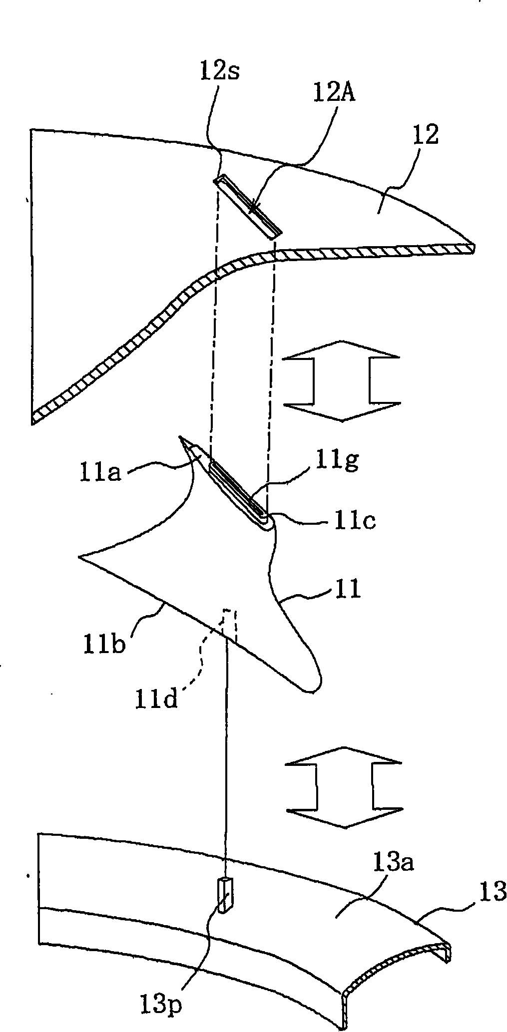
[0075] The blade members 11 are respectively formed of thermoplastic resin such as figure 2 A part of it has two end parts 11a and 11b as illustrated, and is formed into a three-dimensional blade surface shape for the purpose of improving the performance of the turbo blower.

[0076] ...


PUM


Abstract

The invention provides a centrifugal blower and the production method. The centrifugal blower can reduce the operating procedure in the assemble joint and improve the intensity and size precision when jointing three components namely a blade component and two support boards respectively connected with the end of the blade component. The production method of the centrifugal blower ensures a protuberance forming at the end communicating a through hole forming at a main board and ensures the front end of the protuberance expose from the main board when having trail installation to the three components. Secondly, when the main board and the protecting cover are jointed at a plurality of blade components, the front end of the protuberance is supplied with vibration energy using a welding head and the pressure is applied. At the same time of jointing the protecting cover and the end or after the jointing, the front end of the protuberance is supplied with vibration energy and the pressure is applied, to ensure the front end of the protuberance is jointed at the shoulder of the through hole of the main board after the protuberance is fused, thereby supplying vibration energy to the main board as well as applying pressure to joint the main board and the end.

Description

technical field [0001] The present invention relates to a centrifugal fan used in air-conditioning equipment such as air conditioners and the like, and a method for producing the same. Background technique [0002] The centrifugal fan is formed in a shape in which a plurality of blade members arranged at intervals around one axis are sandwiched by two support plates. As a method of manufacturing the centrifugal fan, the cost of a mold is important. The advantages in manufacturing, such as reduction of molding costs, are generally that the blade member is integrally formed on one of the support plates in advance to become a semi-finished product, and ultrasonic welding, laser welding, or solvent welding is used to weld the other support plate. It is attached to the end part of the blade member of the said semi-finished product (for example, refer patent document 1). [0003] [Patent Document 1] Japanese Patent Laid-Open No. 2006-29320 (page 4 [0022]) [0004] Figure 8 It i...

Claims


Application Information

Patent Timeline
Patent Type & Authority Applications(China)
IPC IPC(8): F04D29/28F04D29/60
CPCB29C65/08B29C65/607B29C66/124B29C66/30223B29C66/5344B29C66/5346B29C66/543B29C66/8322B29C66/8432B29L2031/08
Inventor 河合孝小林功
Owner 日本高分子株式会社
Why Eureka
Try Eureka