Osteosynthesis device

A technique of osteosynthesis and central axis, which is applied in the directions of internal bone synthesis, surgery, medical science, etc., and can solve the problem of patients not being able to work.

Inactive Publication Date: 2008-05-07
SYNTHES GMBH
View PDF1 Cites 4 Cited by
  • Summary
  • Abstract
  • Description
  • Claims
  • Application Information

AI Technical Summary

Problems solved by technology

The disadvantage of this known technique is that the patient can hardly work since he has to wear a "bumper" (e.g. hard rails)

Method used


Image

  • Osteosynthesis device
  • Osteosynthesis device
  • Osteosynthesis device

Examples


Embodiment Construction

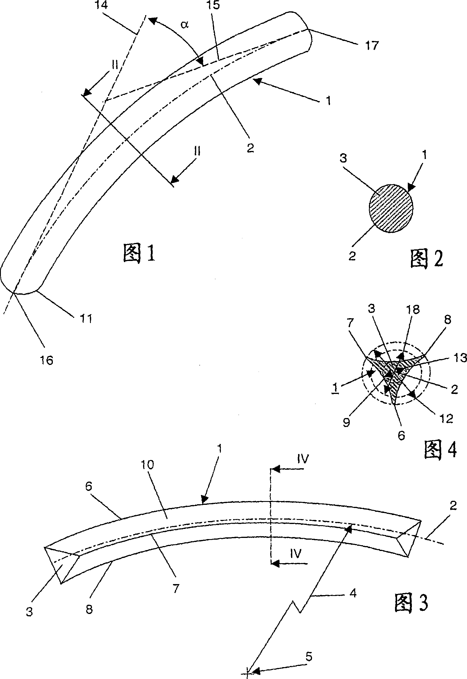
[0059] The device shown in FIGS. 1 and 2 for temporary splinting of toes, in particular for the treatment of hammer toes or other toe dislocations, basically comprises a curved rod 1 having a central axis 2 and A non-circular (here oval) cross-section 3, the rod is made of a material preferably self-reinforced poly L,D lactic acid (SR-PLA 96 / 4). Copolymers of poly-L-lactic acid (PLLA) and poly(DL-lactic-glycolic acid polymer) (PLGA), preferably in a ratio of 4:1, are also suitable for this purpose. A mixture of 96% poly-L-lactic acid (PLLA) and 4% poly-D-lactic acid also proved to be advantageous.

[0060] The rod 1 has a bend in the plane of the drawing with a radius of curvature having a length of 10 cm. The tangents 14 , 15 at the two end points 16 , 17 of the central axis 2 of the rod 1 intersect here at an angle α of 5° to 20°, typically 15°. The length of rod 1 is 3.75 cm. The surface of the rod 1 is completely smooth. The end 16 of the rod 1 for insertion into the t...


PUM


Abstract

The present invention relates to an osteosynthesis device which is used, in particular, for securing joint fragments and for the temporary splinting of toes, more particularly for treating hammer toes or other malalignments of toes. The device comprises a pin (1) with the centre axis (2) and the length L, the pin consisting largely of a bioresorbable material. The pin (1) has at least in one section of the length L a non-circular cross-section (3) that is orthogonal to the centre axis (2) and has a radius of curvature.

Description

technical field [0001] The invention relates to a device in the preamble of claim 1 and to an embodiment of the device according to claim 18 comprising a tool set and a drill bit. Background technique [0002] Such devices can be used for various medical indications, in particular: [0003] A) the fixation of articular fragments, i.e. fragments, which include both bony and cartilaginous parts, and [0004] B) For temporary splinting of toes, especially for hammer toes or other misalignment of toes. [0005] Joint fragments occur, for example, in: [0006] a1) in an accident such as a combination of ligament damage and possible dislocation; [0007] a2) chronic joint instability; [0008] a3) Developmental disorders during puberty (so-called osteochondrosis or osteochondritis) [0009] Most of these conditions involve the knee (leg bone), upper ankle (talus) and hip joint (femur). [0010] Joint fragments typically measure between 2 and 30 mm and must be anatomically pr...

Claims


Application Information

Patent Timeline
Patent Type & Authority Applications(China)
IPC IPC(8): A61B17/68A61B17/00A61B17/72
CPCA61B17/7291A61B2017/00004A61B17/68A61B17/72A61B17/58A61B17/86
Inventor K·克劳
Owner SYNTHES GMBH
Why Eureka
Try Eureka