
Apparatus and method to synchronize switching frequencies of multiple power regulators

A technology of power regulators and switching regulators, applied in circuit devices, regulating electrical variables, control/regulating systems, etc.

Inactive Publication Date: 2008-05-07
TEXAS INSTR INC
View PDF0 Cites 4 Cited by
  • Summary
  • Abstract
  • Description
  • Claims
  • Application Information

AI Technical Summary

Problems solved by technology

This is an undesired qualification which can have other adverse side effects

Method used


Image

  • Apparatus and method to synchronize switching frequencies of multiple power regulators
  • Apparatus and method to synchronize switching frequencies of multiple power regulators
  • Apparatus and method to synchronize switching frequencies of multiple power regulators

Examples


Embodiment Construction

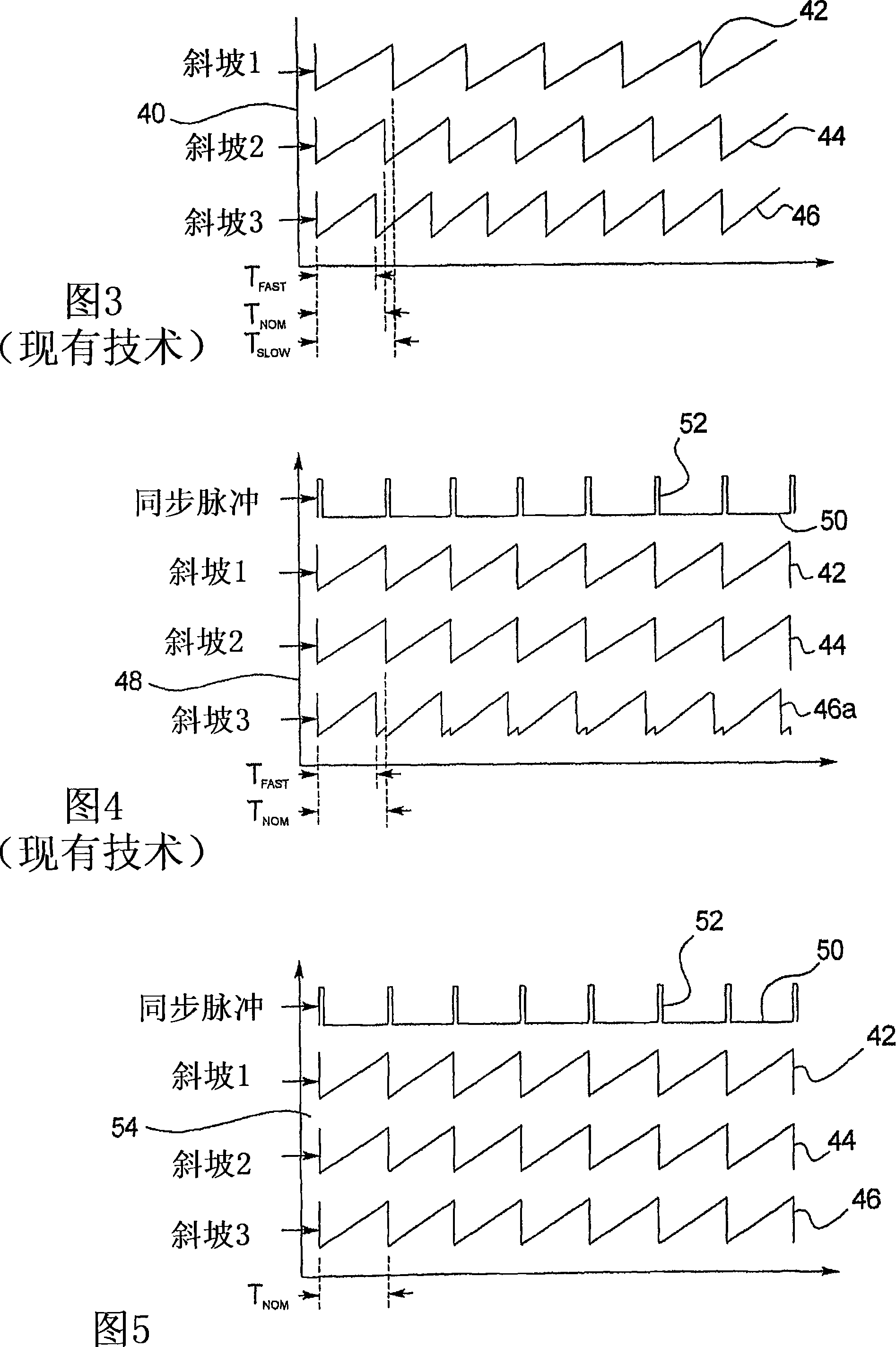
[0021] [0021] The methods and apparatus described enable the signals of multiple power conditioners to be synchronized with each other. Applying the principles of the invention to the previously discussed example, the ramp signals 42, 44 and 46 of the three regulators are mutually synchronized. In particular, in FIG. 5 , ramp 1 signal 42 , ramp 2 signal 44 , and ramp 3 signal 46 are shown along a common timeline in graph 54 , but the multiple signals are shifted to allow for comparison. A sync pulse signal 50 is also shown.

[0022] [0022] Observing the waveform in Fig. 5, it can be clearly seen that after adopting the present invention, the work of the same three power regulators is synchronized to the common signal period T NOM . Now all three regulator signals 42 , 44 and 46 , including regulator signal 46 with the highest free-running frequency, are synchronized to sync pulse signal 50 . All ramp signals exhibit the correct shape for a pulse width modulator such as puls...


PUM


Abstract

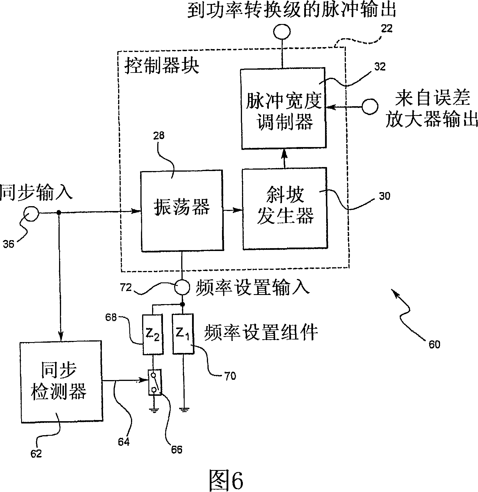
The present invention discloses a power supply (24) having a plurality of switching regulators (150, 152, 154) providing a like plurality of regulated output voltages (1.2V, 1.8V, 3.3V). The oscillators (28) of the switching regulators are synchronized with one another by a synchronization signal (SYNC, INPUT). A synchronization signal detector (62) is provided on one or more of the switching regulators to shift the switching frequency of the oscillator to a lower frequency upon detection of a synchronization signal.

Description

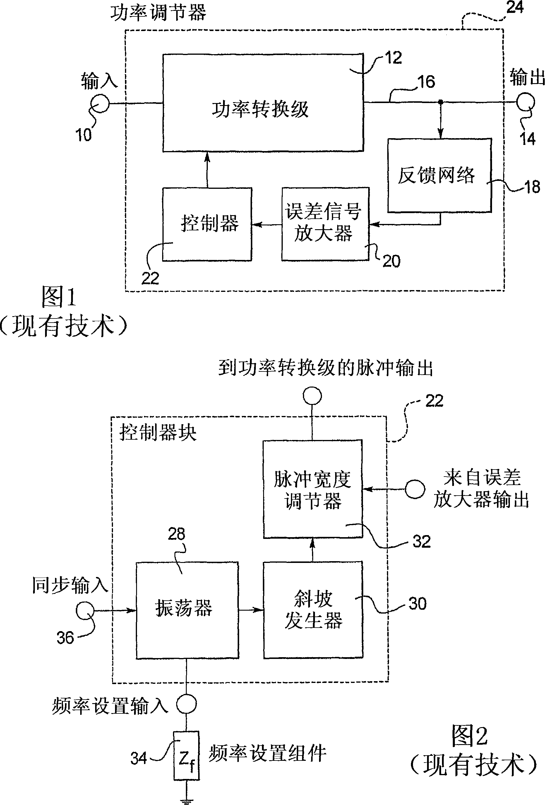
technical field [0001] [0001] The present invention relates generally to power supplies and, more particularly, to an apparatus and method for synchronizing the switching frequency of multiple power regulators. Background technique [0002] [0002] Power conditioners are used in many electrical devices to provide controlled power to circuits in the device. A power regulator can be used to convert voltage to a desired level to regulate power to a specific output level or similar. Power regulators are configured according to several different designs. One such design is a switching power regulator, where the input voltage is switched on and off rapidly and the resulting signal is smoothed to provide a lower level output voltage. In many systems, multiple regulators are used to provide multiple output voltages at different levels. [0003] [0003] A power conditioner 24 including an input 10, a power conversion stage 12, and an output 14 is generally shown in FIG. The output ...

Claims


Application Information

Patent Timeline
Patent Type & Authority Applications(China)
IPC IPC(8): G05F1/59
CPCH02J1/102G05F1/56
Inventor J·N·布拉斯菲尔德J·G·瑞纽尔
Owner TEXAS INSTR INC
Learn More