Mashed potatoes machine for short-order

A potato and mashed machine technology, applied in application, food preparation, food science, etc., can solve the problems of single finished product, customers cannot see the processing process, low efficiency, etc., and achieve high work efficiency, novel design, economical and practical effects

Inactive Publication Date: 2008-05-14
BEIJING JIAOTONG UNIV
0 Cites 6 Cited by

AI-Extracted Technical Summary

Problems solved by technology

The first is large-scale machine processing. This method is efficient, but its finished product is single, and additional auxiliary materials need to be added to make finished mashed potatoes that can be sold, and the processing process cannot ...

Abstract

The invention relates to a potato mesh maker used for fast food, comprising a base, a body, a slide board, a cutting cavity used for cutting potatoes and a feeding rotary cavity used for injecting accessories. The invention is characterized in that the two processing links can be carried out by being integrated into one device. As a good processing equipment for speciality foods, the invention has the advantages of novel design, compact size, economy and practicality, high working efficiency, and special fitness for fast food industry.

Application Domain

Food preparation

Technology Topic

Mechanical engineeringFast foods

Image

  • Mashed potatoes machine for short-order
  • Mashed potatoes machine for short-order
  • Mashed potatoes machine for short-order

Examples

  • Experimental program(1)

Example Embodiment

[0024] Below in conjunction with accompanying drawing 1-12 and embodiment do further description:
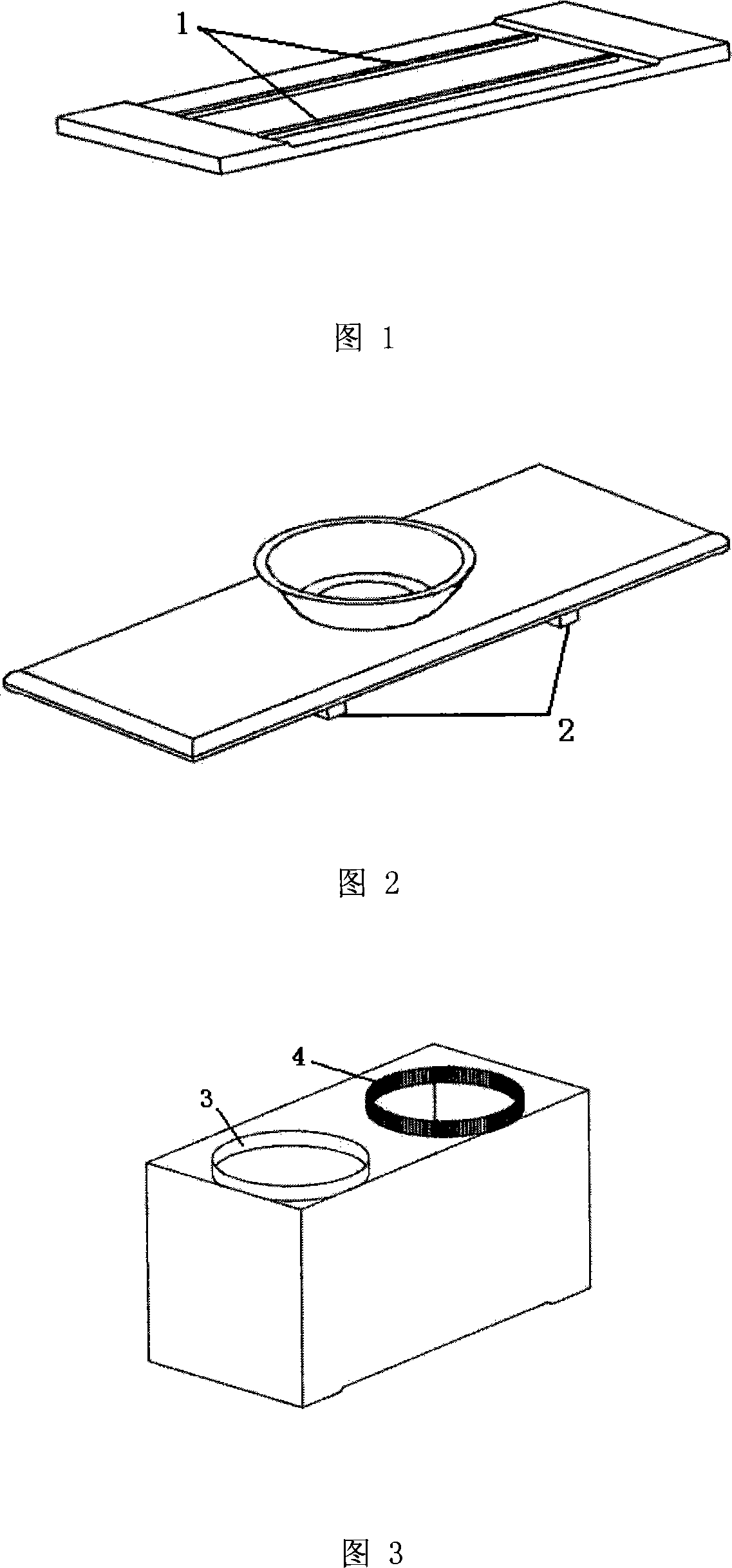
[0025] A mashed potato machine for fast food mainly includes a base, a machine body, a slide plate, a cutting cavity and a feeding rotary cavity.
[0026] The base is a rectangular flat plate with a rectangular groove, and a chute 1 is arranged in the groove.
[0027] There is a rectangular groove corresponding to the base groove at the bottom of the body, and a rectangular slide plate is arranged in the space formed by the base and the groove of the body, and a slide rail 2 corresponding to the base chute is arranged on the plate. A smooth side hole 3 and a toothed side hole 4 are provided on the top surface of the body.
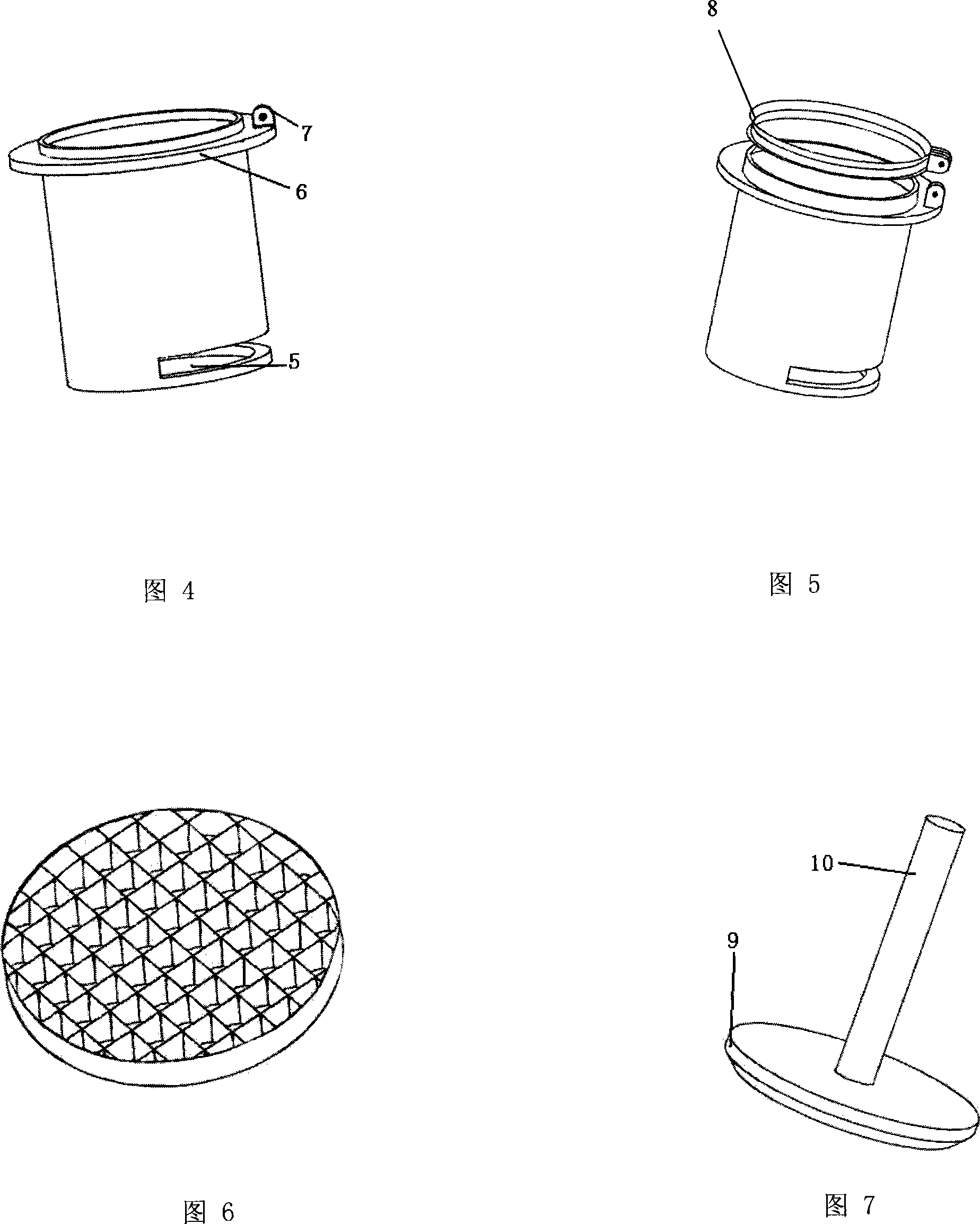
[0028] The cutting cavity is a barrel-shaped cavity set in the smooth edge hole 3 of the body. The lower part of the cavity is provided with a slot 5 for inserting the blade. The blade surface of the blade is grid-shaped, and different shapes can be selected according to the requirements of the user. knife board. The outer upper part of the cavity is provided with a ring plate 6 and a collar 8 connected by a buckle 7, and the pressure plate 9 and the power shaft 10 go deep into the cutting cavity through the collar 8.
[0029] The feeding rotary cavity is a cylindrical cavity set in the tooth edge hole 4 of the machine body. There is an auxiliary material drip hole 11 at the bottom of the rotary cavity, and the drip hole is located at 1/4 of the diameter of the rotary cavity. The ring gear 12 and the cover plate 13, the cover plate 13 has a hole column 14 communicating with the rotary cavity. The short side 16 of the right-angle rotating rod has a positioning hole for the set hole post 14, and the top of the positioning hole is ratchet-connected with the gas cap 15. The long side 17 of right-angle rotating rod is power shaft, and its top 18 is connected air cap top 19 by twisted rope.
[0030] The radius of the feeding rotary cavity is smaller than the radius of the tooth edge hole of the machine body, so it will revolve along the tooth edge hole, and at the same time, the feeding rotary cavity is also rotating. In combination, the dripping trajectory will form a very beautiful pattern.
[0031] Since the inside of the twisted rope can rotate by itself, when the right-angle rotating rod rotates, the twisted rope can also drive the air cap to rotate.
[0032] Since the air cap is ratchet connected with the positioning hole of the right-angle rotating rod, when rotating, most of the time the feeding chamber can be directly connected to the atmosphere, so that the auxiliary materials can be dripped. After the rotation is stopped, the air cap and the positioning hole are closed, and the dripping material stops due to the air pressure, so that the potato masher can automatically control the dripping material.

PUM

no PUM

Description & Claims & Application Information

We can also present the details of the Description, Claims and Application information to help users get a comprehensive understanding of the technical details of the patent, such as background art, summary of invention, brief description of drawings, description of embodiments, and other original content. On the other hand, users can also determine the specific scope of protection of the technology through the list of claims; as well as understand the changes in the life cycle of the technology with the presentation of the patent timeline. Login to view more.

Similar technology patents

Full-automatic ink-jet printer

Owner:KELI ELECTRONICS EQUIP

Take-off assistance device for unmanned aerial vehicle

InactiveCN111619818AInnovative designGood auxiliary effect
Owner:JILIN TEACHERS INST OF ENG & TECH

Indoor environment explosion protection performance testing device for combined flexible explosion protection device

ActiveCN107421823AInnovative designThe evaluation results are reliable
Owner:BEIJING INSTITUTE OF TECHNOLOGYGY

Classification and recommendation of technical efficacy words

  • Innovative design
  • compact structure

Smart home system based on internet of things cloud computing

Owner:中国联合网络通信有限公司物联网研究院

Bionic underwater chelonian robot

InactiveCN101134500ACloselycompact structure
Owner:HARBIN ENG UNIV

Precision vibration damping and locating device

InactiveCN1724892AAccurate positioningcompact structure
Owner:SHANGHAI MICRO ELECTRONICS EQUIP (GRP) CO LTD
Why Eureka
Try Eureka