Roving guide for a stretching unit

A sliver guide and drafting technology, applied in the field of sliver guides, can solve the problem of time-consuming conversion

Inactive Publication Date: 2008-05-14
MASCHINENFABRIK RIETER AG
View PDF0 Cites 4 Cited by
  • Summary
  • Abstract
  • Description
  • Claims
  • Application Information

AI Technical Summary

Problems solved by technology

For a textile machine, ring spinning machines in particular often have more than 1000 drafting units and correspondingly the same number of sliver guides, so changeovers are very time-consuming

Method used


Image

  • Roving guide for a stretching unit
  • Roving guide for a stretching unit
  • Roving guide for a stretching unit

Examples


Embodiment Construction

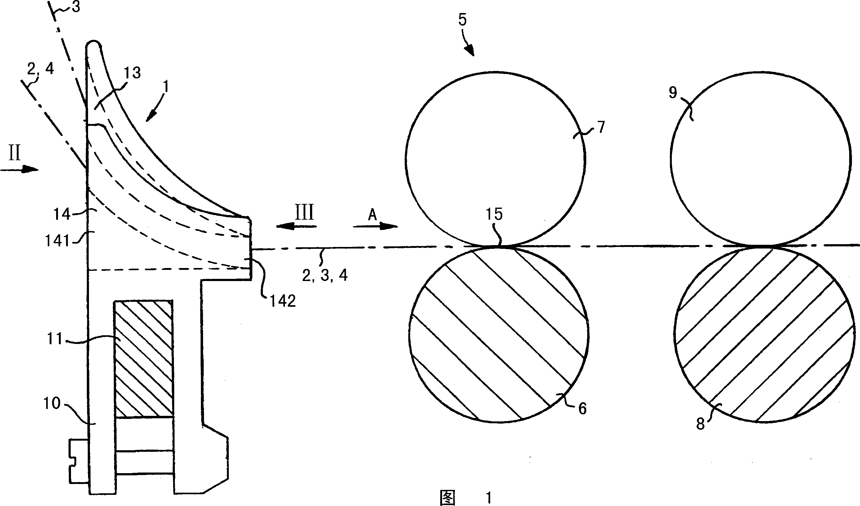
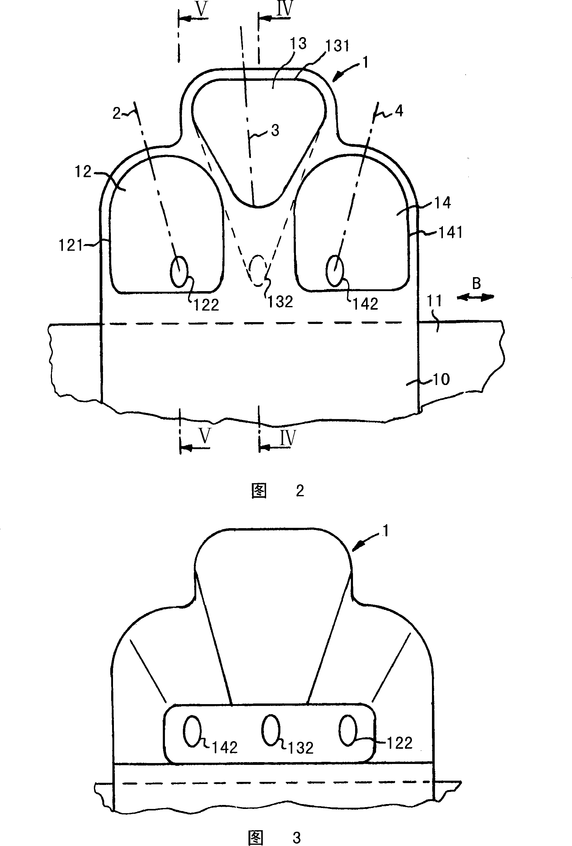
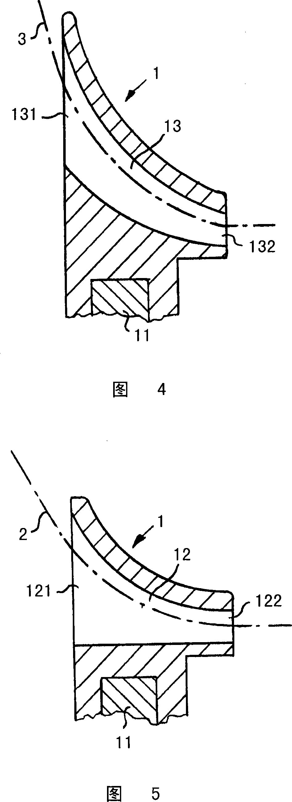
[0020] The sliver guide 1 shown in FIGS. 1 to 5 serves to feed one or two fiber slivers, rovings or card slivers 2 , 3 and 4 to a drafting unit 5 . The drafting mechanism 5 consists of a plurality of roller pairs, of which only two roller pairs 6, 7 and 8, 9 are shown in FIG. 1 .

[0021] There are driven bottom rollers 6 and 8 on which each presses a top roller 7 and 9 . In the case of a drafting unit 5 for a ring spinning machine, the bottom rollers 6 , 8 are designed as grooved rollers which run along the machine longitudinal direction. The slivers 2 , 3 , 4 are transported along the fiber transport direction A to the drafting unit 5 and drawn to their desired fineness. It can be provided, in a manner not shown, that a compression device is then arranged on the drafting mechanism 5 after an output drafting roller pair, in which the sliver 2, 3, 4 is compressed and squeezed in the compression zone. pressure. The drawn strands are then fed to a common twisting unit.

[00...


PUM


Abstract

Disclosed is a sliver apparatus for a drafting mechanism of a textile machine, which is provided with more than two guiding funnels and a roller pair used fro conveying at least a carding sliver to the drafting mechanism, wherein, the guiding funnels are at least partly located at different height, preferably, 3 guiding funnels are set and the entrance position of the middle guiding funnel is higher than those of the other two ones, and the exports of the guiding funnels can be located at the same height.

Description

technical field [0001] The invention relates to a sliver guide for a drafting unit of a textile machine, which has more than two guide funnels for feeding at least one raw sliver to a roller pair of the drafting unit. Background technique [0002] A sliver guide is used in a drafting unit for drafting a fiber sliver for feeding at least one fiber sliver or at least one green sliver to a pair of feed rollers of the drafting unit. In textile machines, for example in ring spinning machines, several drafting units are usually arranged next to each other. The distance between the drafting units is also called "gauge" in this case. [0003] It is known to feed the sliver to the drafting unit and to draw it to the desired fineness in the drafting unit. The drawn fiber sliver can then be twisted into single yarns after the drafting unit. In another known application, two fiber strands are drawn simultaneously in a drafting unit and then twisted together to form a ply strand. The...

Claims


Application Information

Patent Timeline
Patent Type & Authority Applications(China)
IPC IPC(8): D01H13/04D01H5/72B65H57/00
CPCD01H5/005
Inventor W·莱纳U·斯蒂格梅尔
Owner MASCHINENFABRIK RIETER AG
Why Eureka
Try Eureka