
Cross-talk reduction for active matrix displays

An active matrix and display technology, applied in the field of crosstalk, can solve problems such as optical crosstalk and particle distribution differences

Inactive Publication Date: 2008-05-14
KONINKLIJKE PHILIPS ELECTRONICS NV
View PDF0 Cites 16 Cited by
  • Summary
  • Abstract
  • Description
  • Claims
  • Application Information

AI Technical Summary

Problems solved by technology

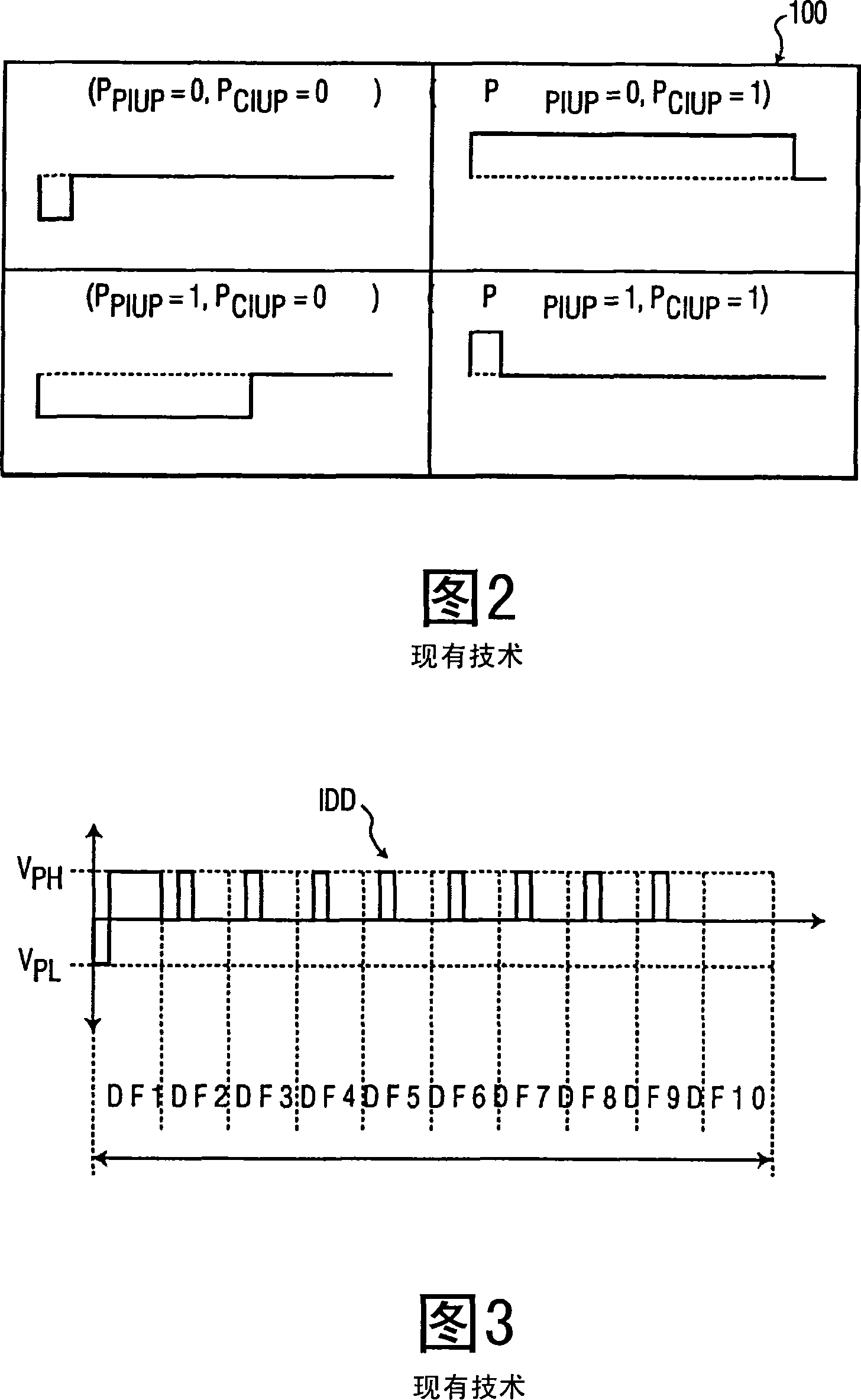
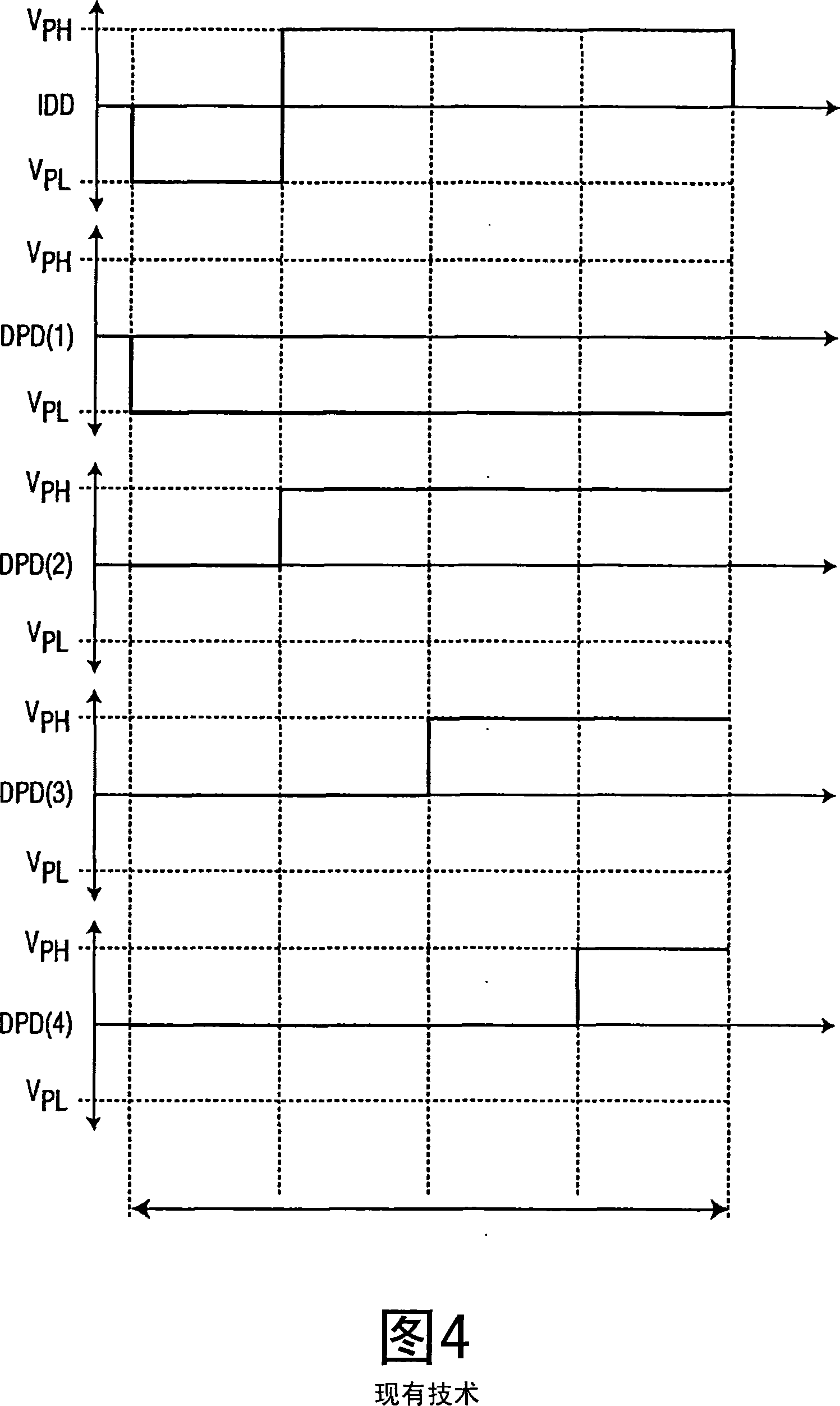
For the remaining drive frames DF2-DF9, there will also be offset differences between the desired pixel data DPD (FIG. 4) and the effective pixel data EPD during the non-selected row address caused by the crosstalk CT, therefore, in the entire The result during the image update period will not be the best image quality for the pixels 21 since each pixel 21 is not properly driven to its respective optimal state
Especially in the case of electrophoretic based active matrix displays, the person skilled in the art will realize that for all drive frames, the difference in offset between the desired pixel data DPD and the effective pixel data EPD will cause a shift in the electrophoretic material. Differences in particle movement velocity, and thus, once actuation is complete, result in differences in particle distribution and thus in gray scale (i.e. optical crosstalk)

Method used


Image

  • Cross-talk reduction for active matrix displays
  • Cross-talk reduction for active matrix displays
  • Cross-talk reduction for active matrix displays

Examples


Embodiment Construction

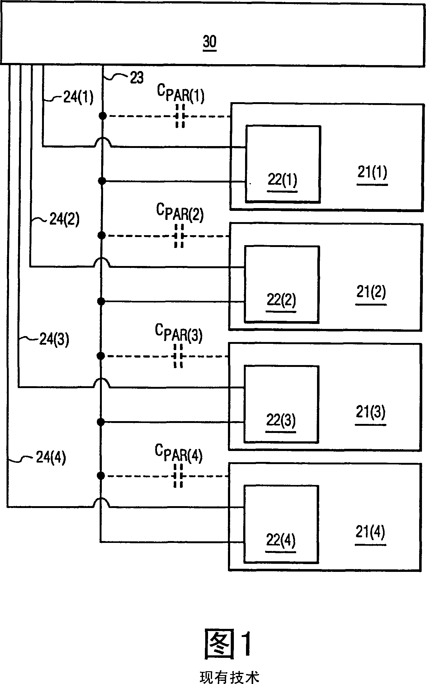
[0030] The schematic representation of pixel 21 (FIG. 1) as shown in FIG. 6 shows that pixel 21 uses a front plate capacitor C connected to pixel node PN and common reference CREF FP , and the storage capacitor C connected to the pixel node PN and the selection line 24 of the preceding pixel 21 STORE . An addressing element in the form of a thin film transistor OTFT is connected to the data line 23, the corresponding selection line 24 and the pixel node PN, whereby during selection of the pixel 21 via the corresponding selection line 24, the data line 23 is directly coupled to the pixel node PN, thus , the image driving data applied to the data line 23 at this time is received and stored in the pixel 21 . When image driving data is applied to the data line 23 and the pixel 21 is not selected via the selection line 24 (Y), a parasitic capacitance C is formed between the data line 23 and the pixel node PN. PAR .

[0031]The image drive data system 40 of the present invention ...


PUM


Abstract

An image drive data system (40) applies cross-talk compensated image drive data (CIDD) to a data line (23) for driving each pixel (21) coupled to the data line (23) to a desired optical state during an image update period inclusive of a cross-talk between the pixels (21) and the data line (23). To reduce the cross-talk, the image drive data system (40) determines cross-talk uncompensated image drive data (IDD) for driving each pixel (21) to its respective desired image exclusive of the cross-talk between the pixels (21) and the data line (23), determines a time averaged pixel data shift based on the cross-talk uncompensated image drive data (IDD) and a cross-talk coupling constant between the pixels (21) and the data line (23), and determines the cross-talk compensated drive data (CIDD) based on the time-averaged pixel data shift.

Description

technical field [0001] The present invention generally relates to crosstalk between pixels and data lines of an active matrix display. In particular, the present invention relates to a technique for reducing this crosstalk to help achieve optimum image quality for the pixels of an active matrix display. Background technique [0002] Polymer Vision is a rollable display currently under development based on a polymer electronic active matrix with electrophoretic display effect. However, in such active matrix displays, there is a certain amount of crosstalk between all pixels and data lines during the image updating process of the active matrix display, which undesirably degrades the image quality of the active matrix display. [0003] For example, FIG. 1 shows four (4) exemplary pixels 21 having address elements 22 operably coupled to data lines 23 and corresponding select lines 24 . During an image update in which the image drive data system 30 applies the image drive data ...

Claims


Application Information

Patent Timeline
Patent Type & Authority Applications(China)
IPC IPC(8): G09G3/20G09G3/34
CPCG09G3/32G09G3/3648G09G2310/061G09G3/20G09G2320/0209G09G2310/06G09G2300/08G09G3/344G09G2310/0248G09G3/30G09G3/34G09G3/36
Inventor N·W·舍林格胡特E·A·胡伊特马
Owner KONINKLIJKE PHILIPS ELECTRONICS NV
Learn More