Connecting mechanism for drawer front faceplate and drawer side surface plate

A connecting device and front panel technology, which is applied in the direction of drawers, furniture connections, connecting components, etc., can solve problems such as poor stability, large shaking range of fixed parts, complex height adjustment structure, etc., to reduce the number of parts, simplify the appearance, and facilitate The effect of adjustment

Inactive Publication Date: 2008-05-21
罗志明
View PDF0 Cites 21 Cited by
  • Summary
  • Abstract
  • Description
  • Claims
  • Application Information

AI Technical Summary

Problems solved by technology

[0003] The current connecting device between the front panel and the side panel of the drawer has the following defects: one is that the rotary slider adopts a single-piece buckle structure to connect with the front yard, and after the connection, the fixed part shakes greatly and has poor stability; There is no loosening mechanism between the connecting frame and the locking bracket. When the front panel of the drawer or the front connecting frame needs to be adjusted, the rotary slider can only be rotated manually to realize the detachment of the front connecting frame and the locking bracket, which is time-consuming and laborious , and it is easy to cause damage to the parts; the third is to adopt a complex height adjustment structure in the adjustment of the height of the main bracket, which increases the process and production cost of the processing operation; the fourth is that the front connection code adopts an integral structure, which is not conducive to Left-right adjustment with drawer front balance

Method used


Image

  • Connecting mechanism for drawer front faceplate and drawer side surface plate
  • Connecting mechanism for drawer front faceplate and drawer side surface plate
  • Connecting mechanism for drawer front faceplate and drawer side surface plate

Examples


Embodiment Construction

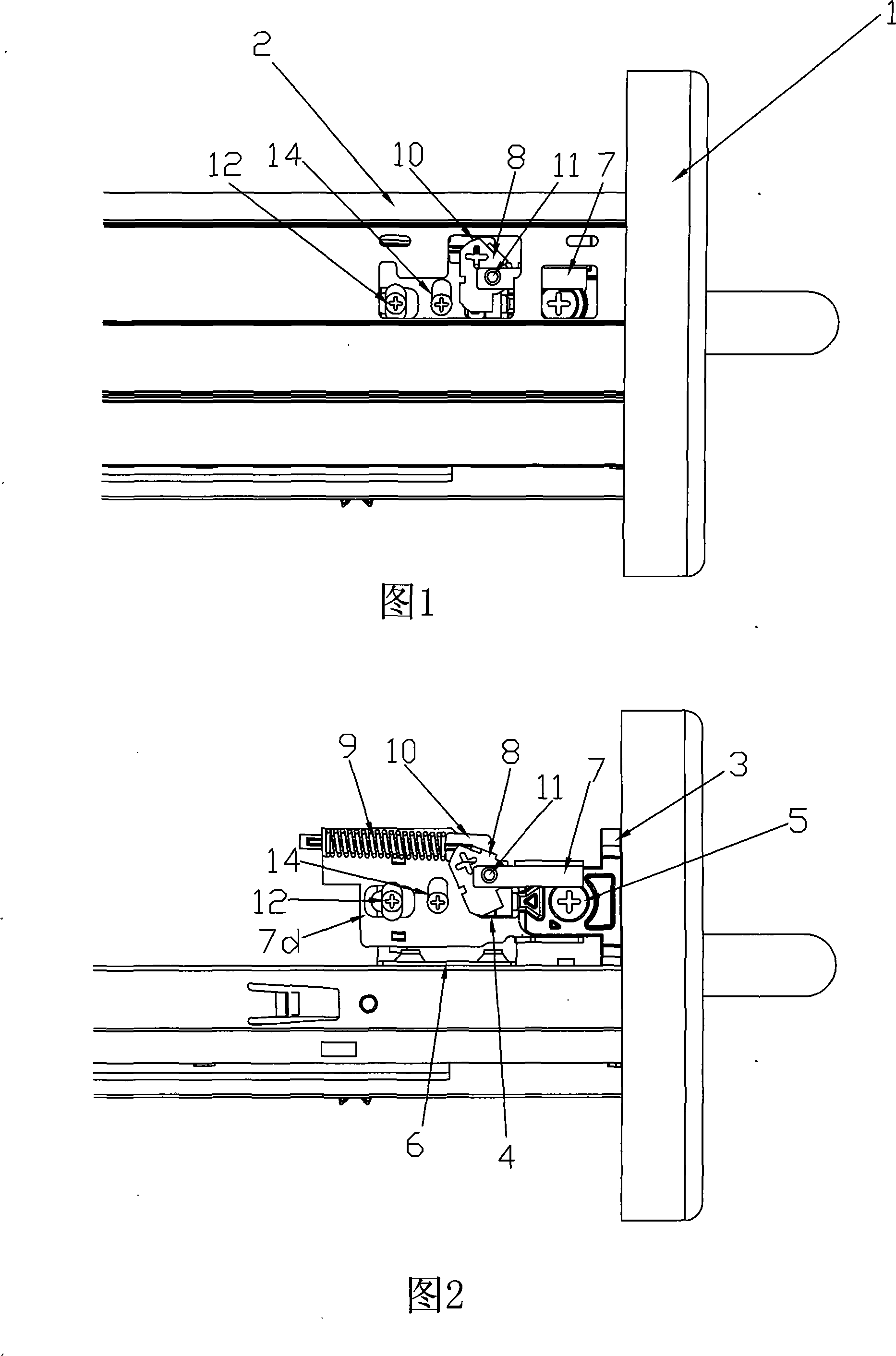
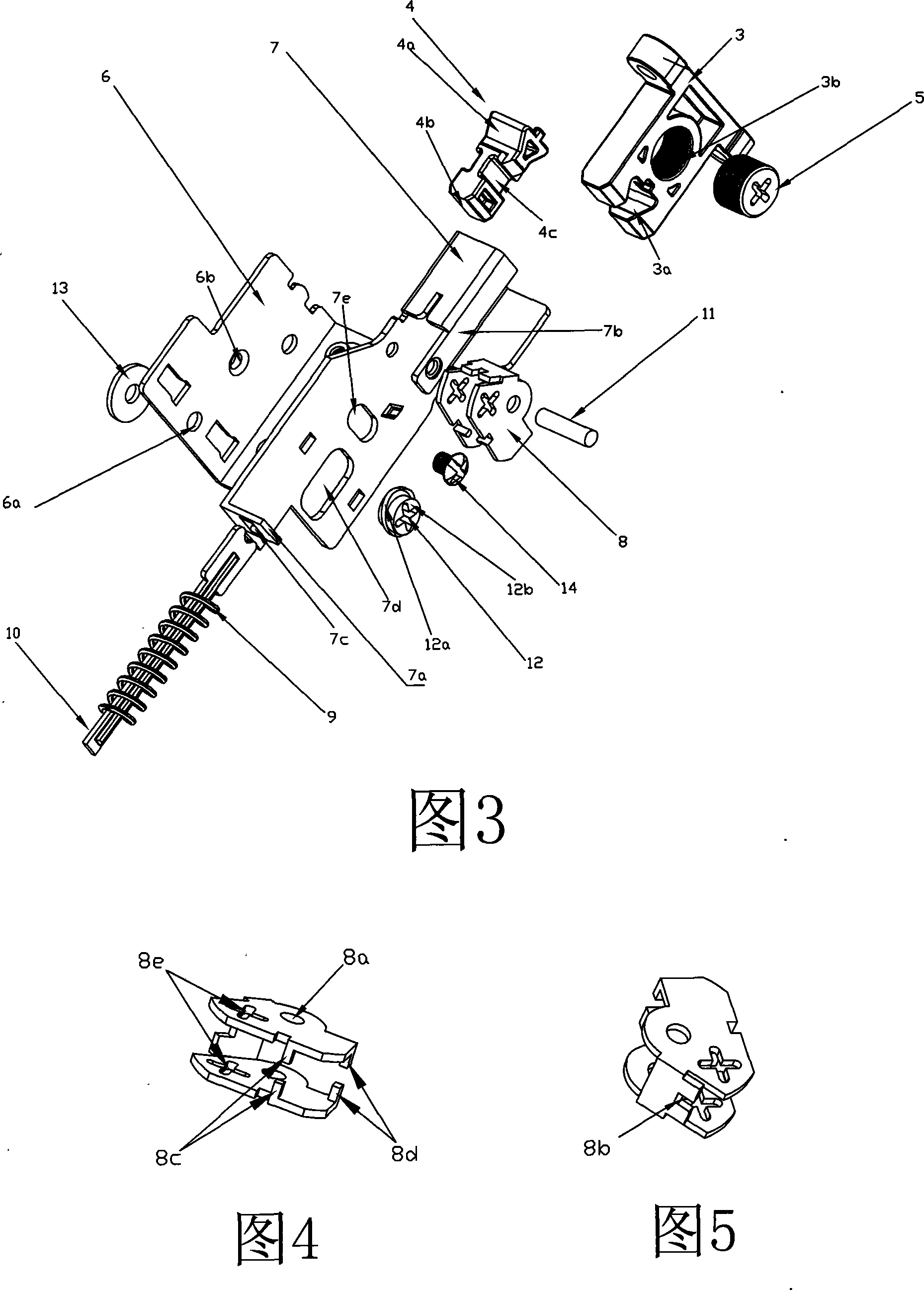
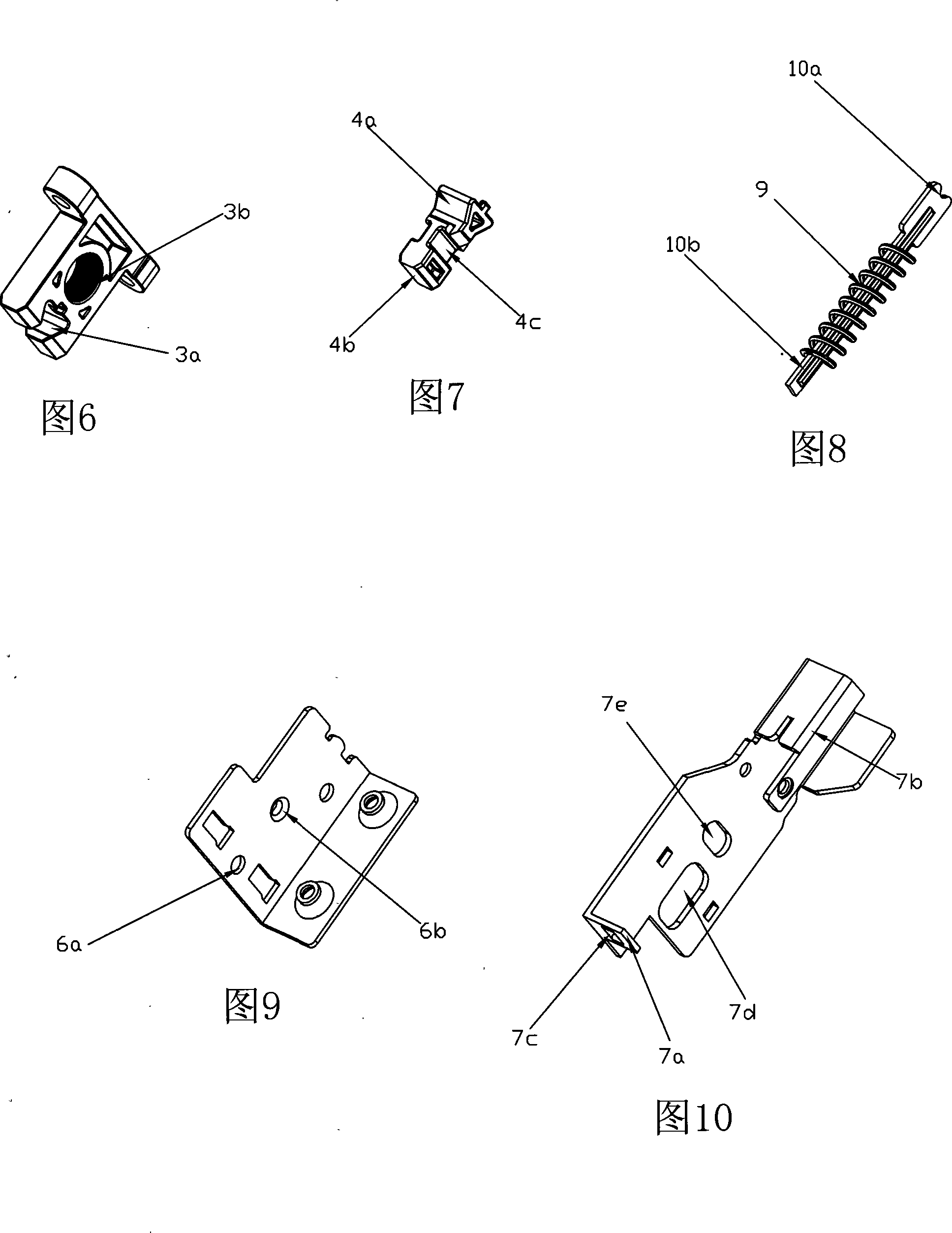
[0036] The connection device between the drawer front panel and the drawer side panel as shown in Fig. 1 to Fig. 13c, the connection device is composed of a front connecting code fixedly installed on the drawer front panel 1 and a locking bracket fixedly installed on the drawer side panel 2 , the front connection code adopts a split structure, which is composed of an insert 3 and an insertion buckle 4, wherein the insert 3 of the front connection code is provided with a trapezoidal guide groove 3a, and the insertion buckle 4 of the front connection code corresponds to the trapezoidal guide groove 3a A trapezoidal chain-in piece 4a is provided at the corresponding position, and the trapezoidal chain-in piece 4a can slide in the trapezoidal guide groove 3a. By inserting the trapezoidal chain-in piece 4a into the trapezoidal guide groove 3a, the inserter 3 and the insertion buckle 4 are connected , the insert 3 of the front code is fixedly connected with the drawer front panel 1, ...


PUM


Abstract

The invention discloses a connecting device of a drawer front panel and a drawer side panel, which consists of a forward-aligned code fixedly arranged on the drawer front panel and a locking bracket fixedly arranged on the drawer side panel; the forward-aligned code is provided with a end face trigger and a locking groove which has the locking slot structure that has two-side symmetry; the locking groove comprises a bottom board, a main bracket, a rotary sliding block, a spring and a lever; the forward alignment code is inserted into the guiding groove of the main groove; the end face trigger of the forward-aligned code collides with the triggering baffle of the rotary sliding block, causing the rotary sliding block to rotate and the locking buckle of the rotary sliding block buckles the locking groove of the forward alignment code, locking the forward-aligned code and connecting the drawer front panel and the drawer side panel. The rotary sliding block of the invention adopts a fan-shaped sliding block of double-layer symmetric structure and the forward-aligned code is of double-faced symmetric locking groove structure and the double-layer rotary sliding block is provide with two symmetric locking buckles that are connected with the locking groove, thus ensuring the forward alignment code and the drawer front panel are stably to be fixed on the drawer side panel.

Description

technical field [0001] The invention relates to a connection device for furniture, in particular to a connection device between a drawer front panel and a drawer side panel. Background technique [0002] Furniture is an indispensable item in people's daily life. In the drawer of its parts, the front panel and the side panel of the drawer are connected by a connecting device. Usually, the connecting device is fixedly installed on the front panel of the drawer. The locking bracket on the side panel is composed of a rotating slider that can be fastened with the front code in the locking bracket. Makes the connection between the drawer front panel and the drawer side panel. [0003] The current connecting device between the front panel and the side panel of the drawer has the following defects: one is that the rotary slider adopts a single-piece buckle structure to connect with the front yard, and after the connection, the fixed part shakes greatly and has poor stability; Ther...

Claims


Application Information

Patent Timeline
Patent Type & Authority Applications(China)
IPC IPC(8): A47B88/04F16B12/00
Inventor 罗志明
Owner 罗志明
Why Eureka
Try Eureka