Major-minor multi-push injection mold pushing mechanism

A top type, main and auxiliary technology, applied in the field of main and auxiliary multi-top injection molding top mold mechanisms, can solve the problems of reduced service life of the mold, excessive support rod diameter, uneven force on the template, etc., to prolong the service life, occupy The effect of small space and easy processing and assembly

Active Publication Date: 2008-05-21
广州一道注塑机械股份有限公司
View PDF0 Cites 3 Cited by
  • Summary
  • Abstract
  • Description
  • Claims
  • Application Information

AI Technical Summary

Problems solved by technology

There are following defects in this top mold mechanism: (1) the diameter of the support rod is too large, and it takes up a lot of space
(4) Reduce the service life of the mold
The number of ejector rods is small, so that the mold is subjected to uneven force, easy to deform, and accelerates mold wear
(5) Leading to template explosion
Long-term uneven force on the formwork can easily cause the formwork to explode

Method used


Image

  • Major-minor multi-push injection mold pushing mechanism
  • Major-minor multi-push injection mold pushing mechanism
  • Major-minor multi-push injection mold pushing mechanism

Examples


Embodiment

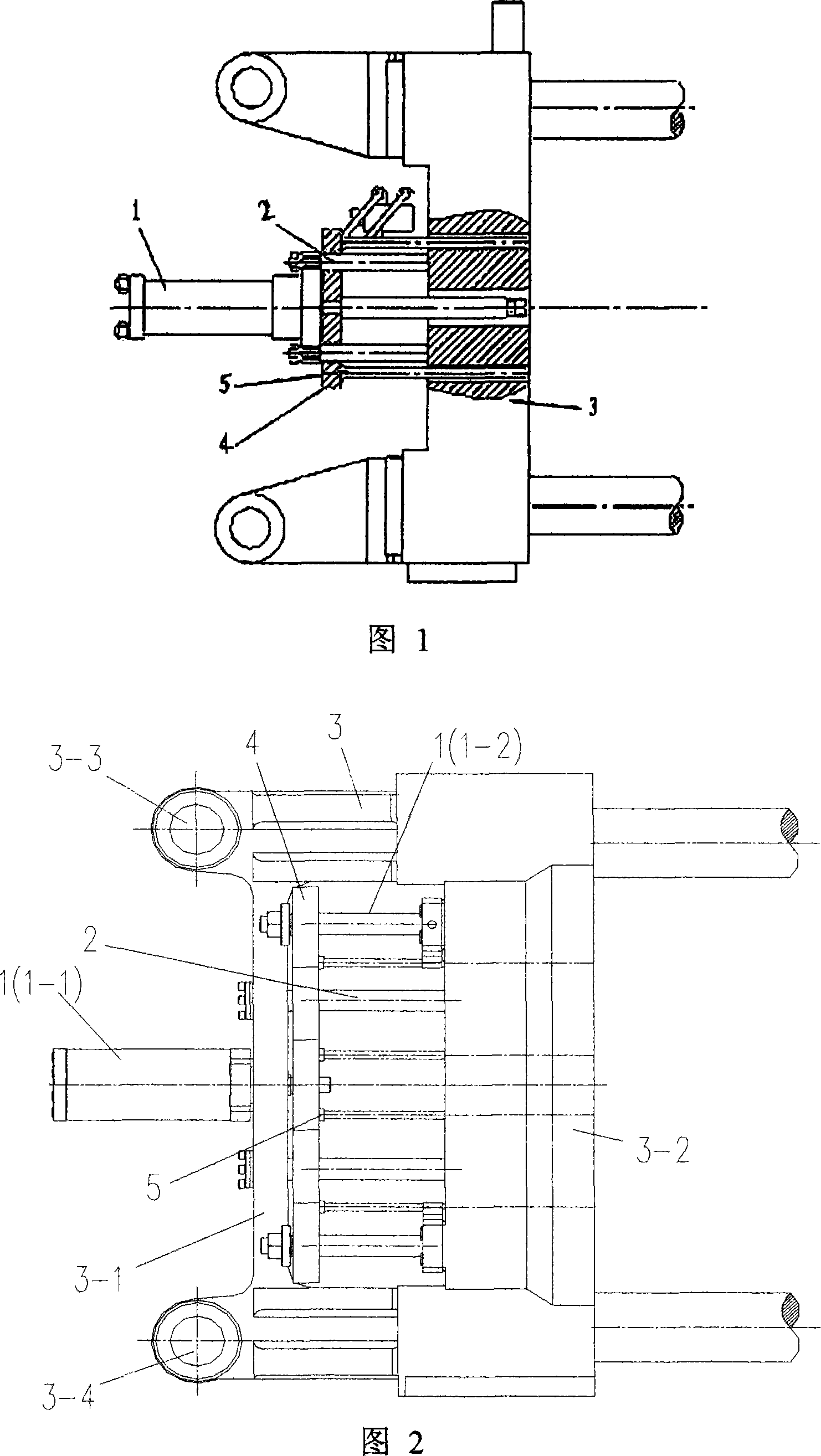
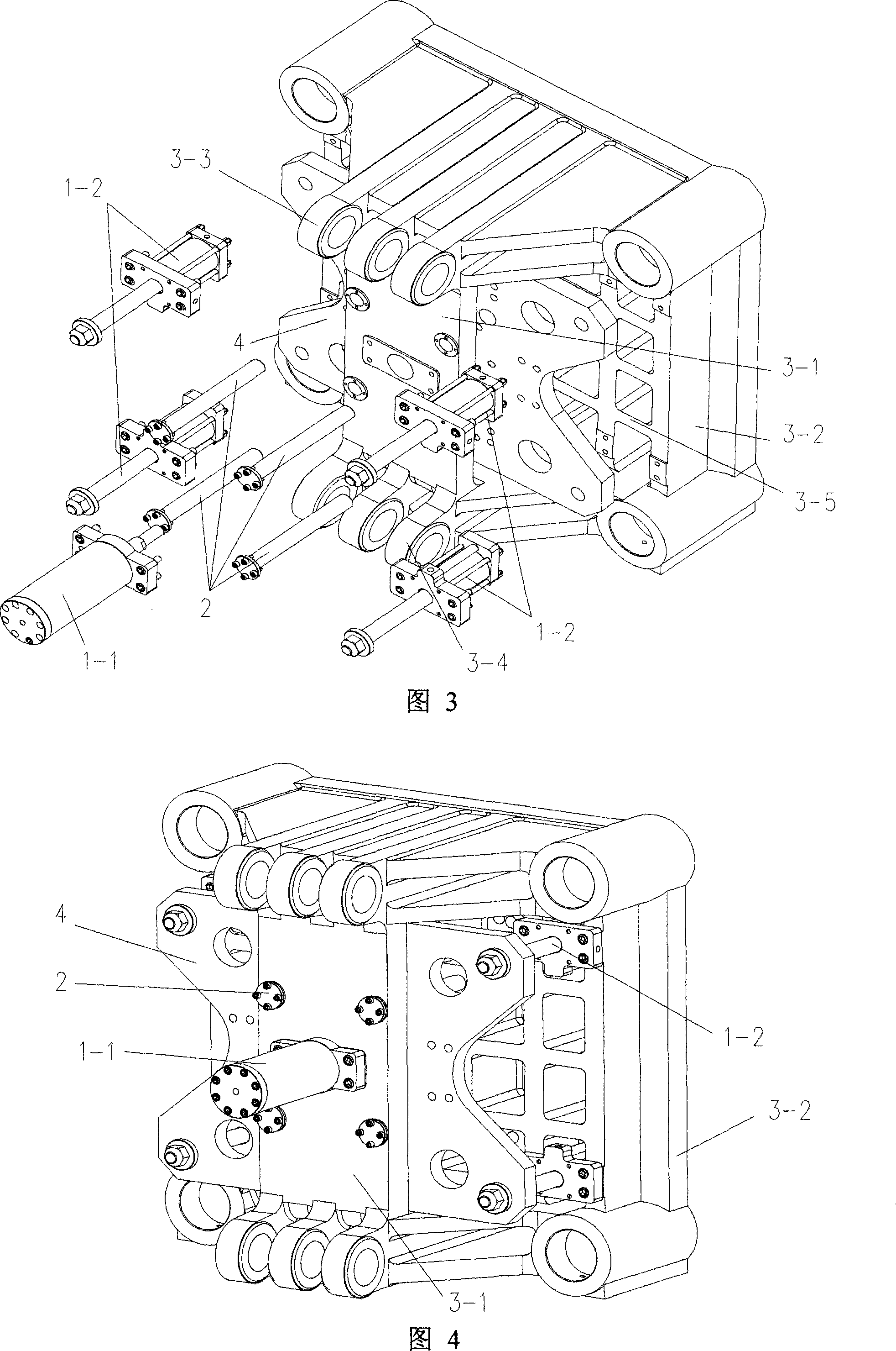
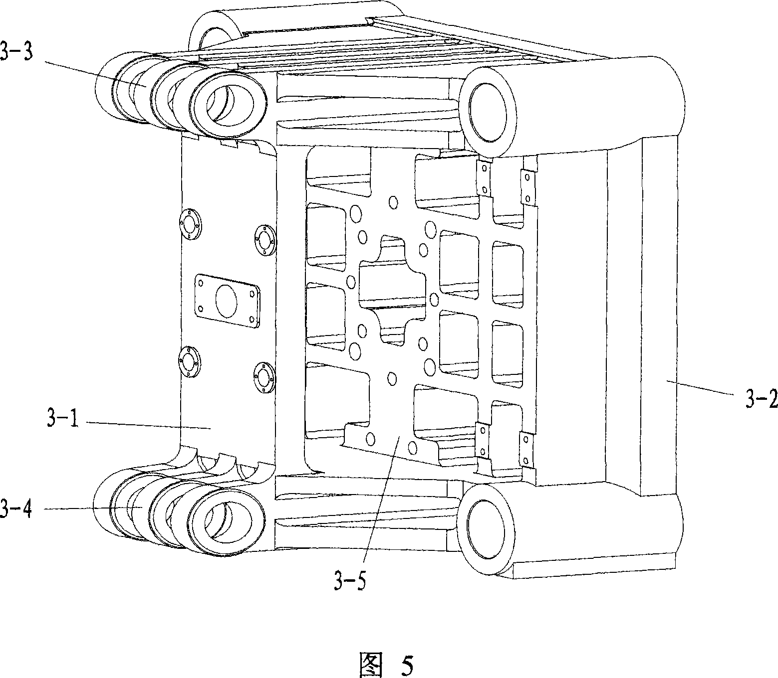
[0026] Figures 2 to 5 show a specific structure of the present invention. It can be seen from Figures 2 to 5 that the main and auxiliary multi-top injection molding top mold mechanism includes a movable template 3, an ejection cylinder 1, a support rod 2, an ejector Ejector plate 4, ejector rod 5, the ejector plate 4 is connected with the ejector rod passing through the movable template 3, the structure of the movable template 3 is shown in Figure 5, and a rib plate 3-1 is provided, so The rib plate 3-1 connects the upper and lower hinge parts 3-3, 3-4 of the movable template 3, and is parallel to the movable template main body 3-2, and the ejector plate 4 is located between the rib plate 3-1 and the movable template main body 3. -2, the support rod 2 passes through the ejector plate 4, and the two ends are fixedly connected with the rib plate 3-1 and the movable formwork main body 3-2, and the ejector cylinder 1 includes a main ejector cylinder 1 -1 and four auxiliary ejectio...


PUM


Abstract

The invention provides a main and auxiliary multi-top injection molding top mold mechanism, which includes a movable template, an ejection cylinder, a support rod, an ejector plate, and an ejector rod, and the ejector plate is connected with an ejector rod passing through the movable template , characterized in that: the movable template is provided with ribs, the ribs are parallel to the main body of the movable template, the ejector plate is located between the ribs and the main body of the movable template, the support rod passes through the ejector plate, The two ends are fixedly connected to the rib plate and the main body of the movable formwork respectively. The ejection cylinder includes a main ejection cylinder and an auxiliary ejection cylinder. The main ejection cylinder is directly connected to the rib plate, and its piston rod is connected to the ejector plate. connected, the auxiliary ejector cylinder is installed on the main body of the movable template, and its piston rod is also connected with the ejector plate. The ejector mold mechanism has sufficient strength and rigidity, and the ejection force is large and uniform, so that the force on the mold is evenly balanced, which can prolong the service life of the mold and effectively improve production efficiency and product qualification rate.

Description

technical field [0001] The invention relates to an injection molding top mold structure, in particular to a main and auxiliary multi-top injection molding top mold mechanism. Background technique [0002] The ejector mechanism of the injection molding machine is used to eject the molded product from the mold. Most of the existing injection molding machines adopt a single-cylinder direct-push top mold mechanism. This type of top mold mechanism is shown in Figure 1. The ejector cylinder 1 is fixedly connected with the movable template 3 through the support rod 2, the ejector plate 4 is connected with the piston rod of the ejector cylinder 1, and the ejector plate 4 is connected with the ejector plate at the same time. The rods 5 are connected, and the support rod 2 passes through the ejector plate 4, which is equivalent to the guide rod of the ejector plate 4, and the ejector plate 4 can be driven by the ejector cylinder 1 to move along the support rod 2. There are following...

Claims


Application Information

Patent Timeline
IPC IPC(8): B29C45/40
Inventor 徐志江易恒光冯良为
Owner 广州一道注塑机械股份有限公司
Why Eureka
Try Eureka