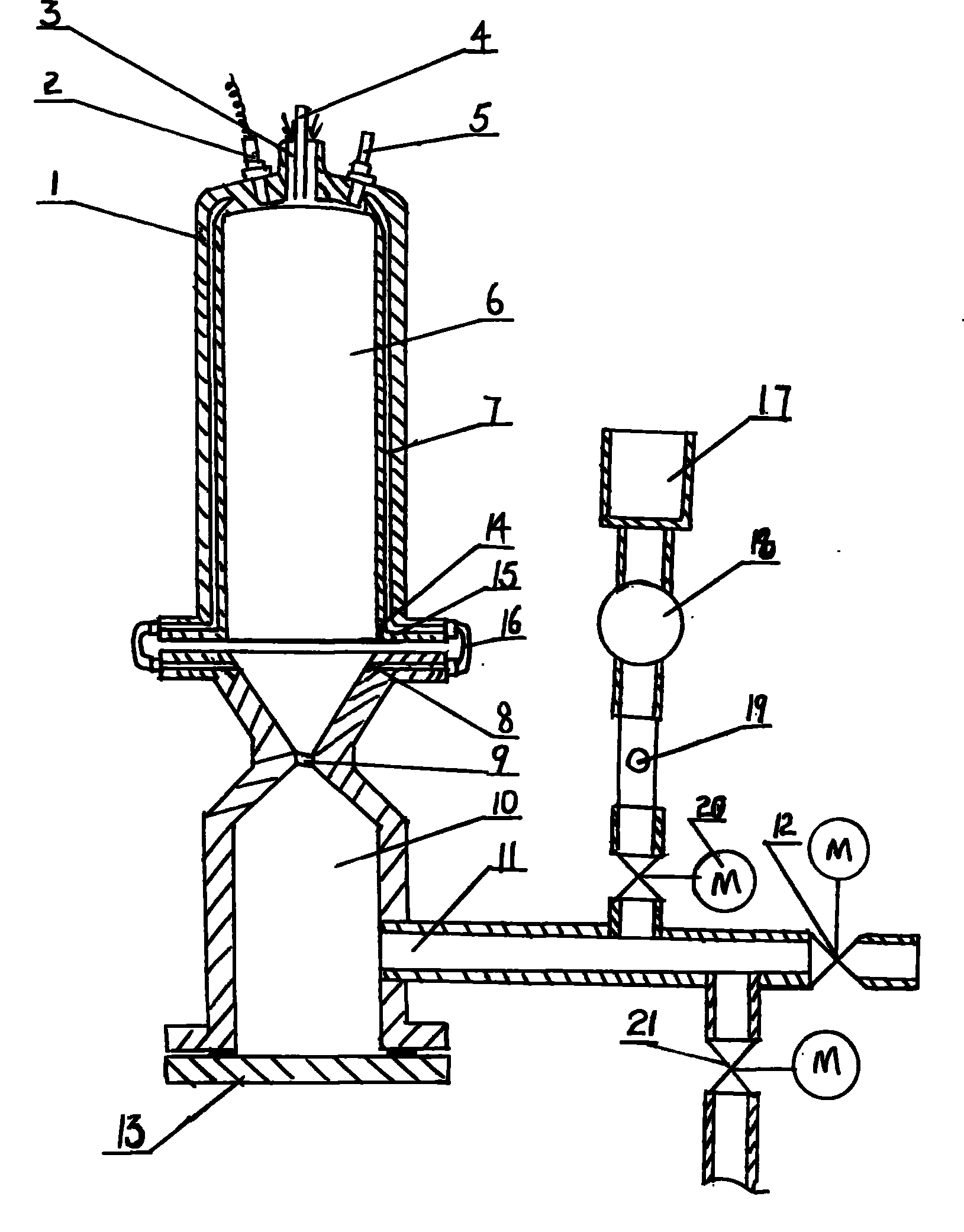
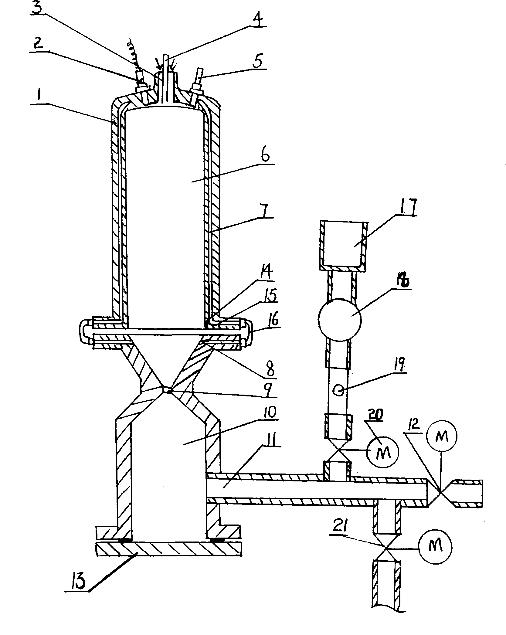
High-temperature mixer generators plant
A complete set of equipment, high-temperature mixing technology, applied in the fields of production fluid, wellbore/well components, earth-moving drilling, etc., can solve problems such as polluting the environment, achieve extended service life, sufficient combustion process and vaporization mixing process, and improve cooling effect. Effect
Inactive Publication Date: 2010-11-10
刘铭 +1
View PDF2 Cites 0 Cited by
- Summary
- Abstract
- Description
- Claims
- Application Information
AI Technical Summary
Problems solved by technology
The injection of chemical agents can be adjusted at any time according to the oil well geology and reservoir pressure changes. While improving the efficiency of crude oil extraction, it can significantly save energy, reduce costs, and effectively solve the problems of environmental pollution in existing technologies.
Method used
View moreImage
Smart ImageViewing Examples
Examples
Embodiment Construction
Login to View More PUM
 Abstract
A high-temperature mixer and generator complete equipment includes a main body consisting of a combined head, a combustion chamber and a buffer chamber, and a cooling circulating water system. A subsonic nozzle is arranged between the lower end of the combustion chamber and the buffer chamber so as to communicate these two chambers; a gasified water system is arranged on the lower end of the internal wall of the combustion chamber and on the upper part of the subsonic nozzle; the buffer chamber is communicated with an underground oil layer through the pipeline of a one-way gas injection valve; the pipeline of the buffer chamber communicated with the underground oil layer is provided with a drain valve; the present invention is characterized in that the pipe of the buffer chamber communicated with the underground oil layer is also provided with a chemical drug injection device. The present invention integrates the technology of gas oil-displacing and chemical oil-displacing in the thick-oil thermal extraction and adjusts the injection of the chemical drug according to the geological features of the oil well and pressure changes of oil reservoir. While increasing the mining efficiency of the crude oil, the present invention can significantly save the energy and reduce the cost, and effectively solve the environmental pollution in the prior technology.
Description
Complete set of high temperature gas mixture generator technical field The invention relates to a composite gas injection device for thermal oil recovery that can replace a boiler, in particular to a complete set of high-temperature mixed gas generator, which belongs to special supporting equipment for oilfield exploitation. Background technique At present, my country's oilfields have abundant heavy oil resources to be exploited. Conventional cold recovery methods are unable to recover heavy oil. Generally, high-pressure steam generated by surface boilers is injected into downhole oil layers for thermal oil recovery. However, there are still many problems in the existing steam injection thermal extraction technology, such as the use of boilers to generate steam with large heat loss, high energy consumption, high equipment and production costs, certain pollution to the environment, and low crude oil extraction efficiency, especially the entire injection device. Poor mobili...
Claims
Login to View More Application Information
Patent Timeline
 Patent Type & Authority Patents(China)
IPC IPC(8): E21B43/16E21B43/24E21B43/22
Inventor 刘铭刘琳燕
Owner 刘铭
Features
- R&D
- Intellectual Property
- Life Sciences
- Materials
- Tech Scout
- Unparalleled Data Quality
- Higher Quality Content
- 60% Fewer Hallucinations
Learn More Browse by: Latest US Patents, China's latest patents, Technical Efficacy Thesaurus, Application Domain, Technology Topic, Popular Technical Reports.
© 2025 PatSnap. All rights reserved.Legal|Privacy policy|Modern Slavery Act Transparency Statement|Sitemap|About US| Contact US: help@patsnap.com


