Cooling clothes

A technology for cooling clothing and clothing, applied in clothing, apparel, protective clothing, etc., can solve the problems of complex structure of cooling clothing, and achieve the effect of expanding the effective range

Active Publication Date: 2006-09-06
SEFT DEVMENT LAB
View PDF1 Cites 6 Cited by
  • Summary
  • Abstract
  • Description
  • Claims
  • Application Information

AI Technical Summary

Problems solved by technology

[0006] Therefore, the structure of the conventional air-flow cooling suit is complex

Method used


Image

  • Cooling clothes
  • Cooling clothes
  • Cooling clothes

Examples


no. 1 approach

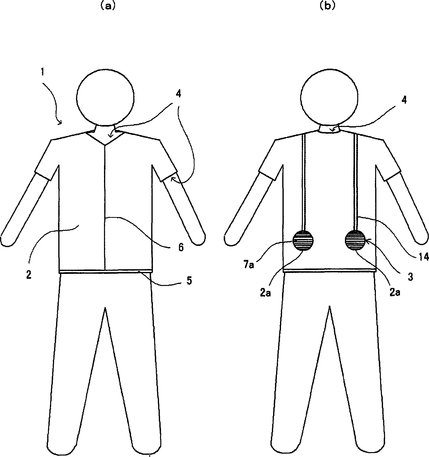
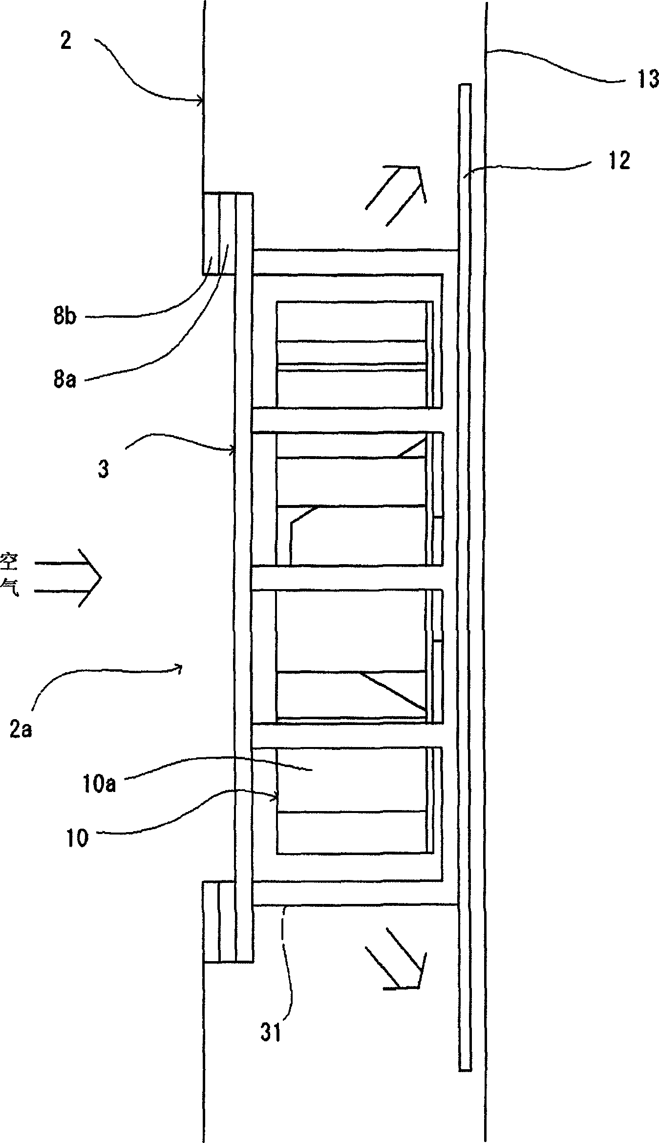
[0065] Hereinafter, the best mode for carrying out the present invention will be described with reference to the accompanying drawings. The first embodiment is an example in which the cooling suit of the present invention is applied to a half-sleeve top for work wear. figure 1 (a) is a schematic front view of the cooling suit according to the first embodiment of the present invention, and (b) is a schematic rear view thereof. like figure 1 As shown, the cooling suit 1 of the first embodiment includes: the garment 2 formed in the shape of a half-sleeve jacket, which has less air leakage and is also used as a flow guide cloth (the meaning of flow guide will be described later); The parallel wind generating device 3 on the left and right of the lower back is used for inhaling external air and generating an airflow parallel to the body between the clothing 2 and the underwear or the body; the air outlet 4 as an air outlet; the function formed on the clothing 2 An air suction por...

no. 2 approach

[0086]Next, a second embodiment of the present invention will be described with reference to the drawings. In the second embodiment, the present invention is applied to work clothes having a higher cooling capacity than the cooling clothes of the first embodiment. The air supply capacity of the second embodiment is double that of the first embodiment, ie 20m 3 / H or so. The main difference between the second embodiment and the first embodiment is that in the second embodiment, as the blade of the parallel wind generating device, a propeller is used instead of the impeller; A new air outlet part of the sheet; and a fixing unit, ie, a fixing belt, is provided to prevent the large fan from shaking due to body movements. Other structures are the same as those of the first embodiment. Therefore, in the second embodiment, the same reference numerals are attached to parts having the same functions as those of the first embodiment, and detailed descriptions thereof will be omitted....

no. 3 approach

[0095] Next, a third embodiment of the present invention will be described. The third embodiment differs from the first and second embodiments in that not only a fan but also a power supply (battery) and a lead wire are attached to the fixing belt. The other points are the same as those of the second embodiment. Therefore, in this embodiment, the same reference numerals are attached to parts having the same functions as those of the first and second embodiments, and detailed descriptions thereof will be omitted. Fig. 10(a) is a schematic view showing a state in which the fixing band 160 of the present embodiment is unfolded. The width of the fixing band 160 of the present embodiment is larger than the diameter of the fan 3 , and the two fans 3 , the lead wire 32 for power supply, and the power source 33 are detachably mounted thereon. Therefore, it can be said that the fixing belt 160 has removed the baffle (clothing) from the cooling suit. FIG. 2(b) is an enlarged schemati...


PUM


Abstract

Cooling clothes formed in a simple structure and capable of securely evaporating a large amount of sweat, comprising an air inlet port (2a) for taking external air therein, a parallel air generating means (3) for taking air from the air intake port therein and generating parallel air generally parallel with a body, a guide sheet used commonly as the clothes (2) for guiding, parallel with the body, the parallel air generated by the parallel air generating means, an air outlet part discharging the parallel air to the outside, and a power supply means for supplying power to the parallel air generating means. The cooling clothes are characterized in that a pressure between the guide sheet and an underwear is made positive to form an air flow space by sending air between the guide sheet and the underwear at a total rate of approximately 5 to 300 m<3> / h by the parallel air generating means, vapor caused by sweat is discharged to the outside and fresh outside air is constantly sent therein by flowing air in the air flowing space to remarkably relieve the conditions under which sweat is allowed to be evaporated.

Description

technical field [0001] The present invention relates to a cooling suit which cools the human body by allowing external air to circulate in parallel with the body. Background technique [0002] People obtain energy by ingesting food to maintain life activities and work, and emit heat accordingly. However, if people are compared to a work device, it can be said that its energy utilization efficiency is very low. Due to the low efficiency, almost all of the ingested energy is converted into heat, and in order to maintain normal body temperature, a large amount of heat dissipation corresponding to the workload at this time must be performed. For this reason, humans have the physiological function of cooling the body through sweating. That is to say, the amount of heat dissipation necessary for the physiology is determined according to the workload, and the corresponding sweat is discharged. If all the sweat is vaporized, the heat dissipation is most suitable for the situation o...

Claims


Application Information

Patent Timeline
Patent Type & Authority Applications(China)
IPC IPC(8): A41D13/00A41D27/28A41D13/002A41D13/02
CPCA41D13/0025A41D31/14A41D13/0056A41D27/28
Inventor 市谷弘司
Owner SEFT DEVMENT LAB
Why Eureka
Try Eureka