Forced-directed oil cooling coil configuration

A technology of strong oil and coils, applied in the field of transformers, can solve the problems of inability to meet the needs of product development, increase in coil loss and geometric size, and inability to distribute oil flow evenly in coils, and achieve longer life, lower flow rate, and better cooling effect. Effect

Active Publication Date: 2008-05-21
TBEA SHENYANG TRANSFORMER GRP CO LTD
View PDF1 Cites 4 Cited by
  • Summary
  • Abstract
  • Description
  • Claims
  • Application Information

AI Technical Summary

Problems solved by technology

However, with the development of power engineering, the application of AC and DC transformers and reactor products is also developing in the direction of high voltage and large capacity, and the loss and geometric size of the coil are also increasing. Only by changing the coil and paper The gap between the barrels can no longer make the oil flow inside the coil evenly distributed, and it can't achieve a good cooling effect, so it can't meet the needs of product development.

Method used


Image

  • Forced-directed oil cooling coil configuration
  • Forced-directed oil cooling coil configuration
  • Forced-directed oil cooling coil configuration

Examples


Embodiment 1

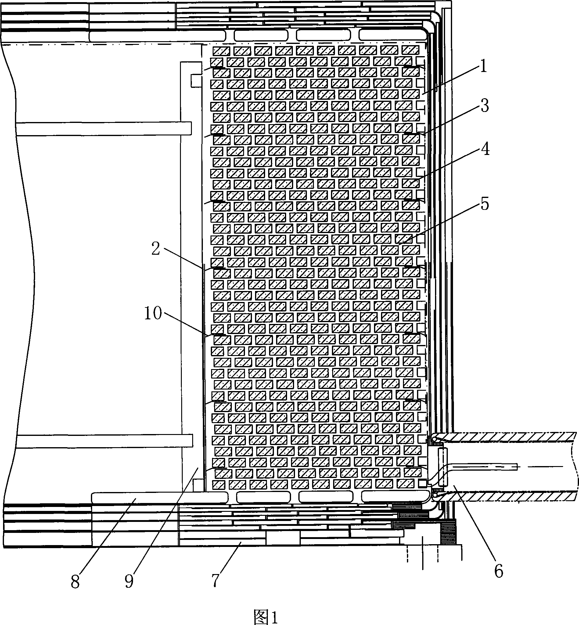
[0019] Embodiment 1: As shown in Figure 1, the present invention includes a ring coil 1, a tensioning structure frame 9, an inner oil baffle 2, an outer oil baffle 3, a first insulating block 8, an end insulation structure 7 of the ring coil and a lead-out The oil blocking structure 6 at the line is arranged inside the ring coil 1 with a brace structure frame 9, and the inside and outside of the ring coil 1 are respectively equipped with an inner oil baffle plate 2 and an outer oil baffle plate 3, and the brace structure frame 9 and the inner oil baffle plate 2. A paper tube 10 is placed between them. An oil blocking structure 6 is provided at the lead-out line at the lower end of the toroidal coil 1. A first insulating block 8 is provided at the upper and lower ends of the toroidal coil 1. At the lower end of the toroidal coil 1, the first insulating block 8 A coil end insulation structure 7 is provided.

[0020] The toroidal coil 1 of this example is composed of several wire...

Embodiment 2

[0024] Embodiment 2: As shown in Figure 1, the present invention includes a ring coil 1, a brace structure frame 9, an inner oil baffle 2, an outer oil baffle 3, a first insulating block 8, a coil end insulation structure 7 and lead wires The oil blocking structure 6 is arranged inside the ring coil 1 with a brace structure frame 9, the inside and outside of the ring coil 1 are respectively equipped with an inner oil baffle plate 2 and an outer oil baffle plate 3, and the brace structure frame 9 and the inner oil baffle plate 2 A paper tube 10 is interposed, and an oil blocking structure 6 is provided at the lead-out line at the lower end of the toroidal coil 1. First insulating blocks 8 are respectively provided at the upper and lower ends of the toroidal coil 1, and a first insulating block 8 is provided at the lower end of the toroidal coil 1. There is a coil end insulation structure 7 .

[0025] The ring coil 1 , the insulation structure 7 at the end of the coil and the oi...


PUM


Abstract

The utility model relates to a coil structure with strong oil guiding and cooling, belonging to the technical field of transformers. Its structure includes a ring coil, a holding structure frame, an inner oil baffle, an outer oil baffle, a first insulating block, an insulation structure at the end of the ring coil and an oil blocking structure at the lead wire, and a holding structure frame is arranged inside the ring coil. There are inner and outer oil baffles on the inner and outer sides of the ring coil, cardboard is arranged between the holding structure frame and the inner oil baffle, an oil resistance structure is provided at the lead-out line at the lower end of the ring coil, and the upper and lower ends of the ring coil are respectively provided with There is a first insulating block, and a coil end insulating structure is arranged at the lower part of the first insulating block at the lower end of the annular coil. The oil volume of the three oil inlets at the end of the toroidal coil of the transformer can be respectively 27.7%, 33.3% and 39%; the oil volume is not much different, and the coil can be effectively cooled. While achieving better cooling effect, the performance of safe and reliable operation of the product is also improved.

Description

technical field [0001] The invention belongs to the technical field of transformers, in particular to a coil structure for strong oil-guided cooling. It can be applied to high-voltage, ultra-high-voltage large-capacity AC and DC transformers and reactor products. Background technique [0002] In the existing coil structure, due to poor heat dissipation conditions, the inner and outer longitudinal oil gaps of the inner coil are small, and the outer longitudinal oil gap of the outer coil is much larger than the inner longitudinal oil gap, so the oil flow through the inner coil is insufficient. The oil flow through the outer coil is excessive, resulting in a mismatch of oil flow between the coils, resulting in a lower temperature rise of the outer coil and a higher temperature rise of the inner coil, which in turn increases the unevenness of the oil flow distribution and increases the oil flow rate. If the temperature is reduced, the cooling conditions will become worse, so th...

Claims


Application Information

Patent Timeline
Patent Type & Authority Applications(China)
IPC IPC(8): H01F27/12H01F27/28
Inventor 王健王平王巍彭博刘向鹏
Owner TBEA SHENYANG TRANSFORMER GRP CO LTD
Why Eureka
Try Eureka