Medical breathing machine

A technology of ventilator and exhalation tube, which is applied in the field of medical equipment, can solve the problems of burning out patients and excessive water accumulation, and achieve the effect of avoiding medical accidents and being convenient and simple to use

Inactive Publication Date: 2018-08-28
LIUZHOU PEOPLES HOSPITAL
View PDF8 Cites 3 Cited by
  • Summary
  • Abstract
  • Description
  • Claims
  • Application Information

AI Technical Summary

Problems solved by technology

[0003] The invention provides a medical ventilator, which can solve the problem of burning out the patient's respiratory tract or water accumulation in the existing medical ventilator, which is easily caused by too little water in the humidification tank or too much water in the water storage cup. Problems blowing back into the patient's lungs

Method used


Image

  • Medical breathing machine
  • Medical breathing machine

Examples


Embodiment 1

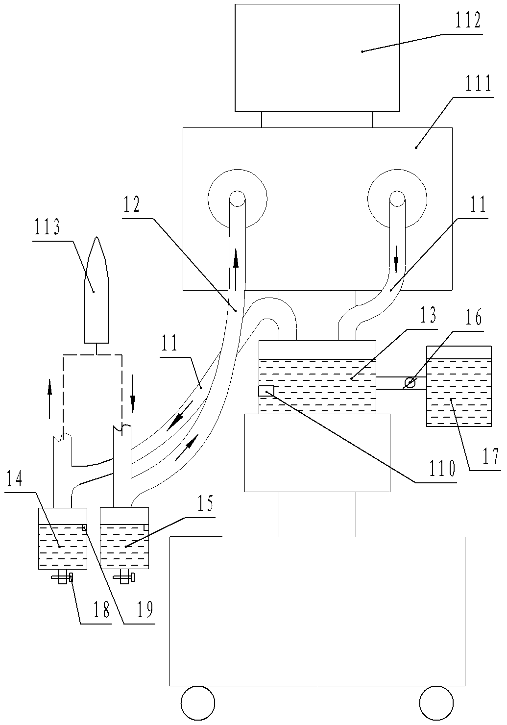
[0021] figure 1 The shown medical ventilator includes an inhalation pipeline 11 and an exhalation pipeline 12 respectively mounted on the control box, and the outlet end of the inhalation pipeline 11 and the inlet end of the exhalation pipeline 12 are inserted into the patient's lung The pipe section is connected with the simulated lung 113; the inhalation pipeline 11 is provided with a humidification tank 13 and the first water storage cup 14 in sequence along the direction from the inlet to the outlet of the inhalation pipeline; the exhalation pipeline 12 is provided with a second Water storage cup 15; the height of the water inlet of the first water storage cup 14 is lower than the height of the steam outlet of the humidification tank 13, and the height of the water inlet of the second water storage cup 15 is lower than the height of the outlet end of the exhalation pipeline 12; there is also a A water tank connected with the water inlet of the humidification tank 13 throug...

Embodiment 2

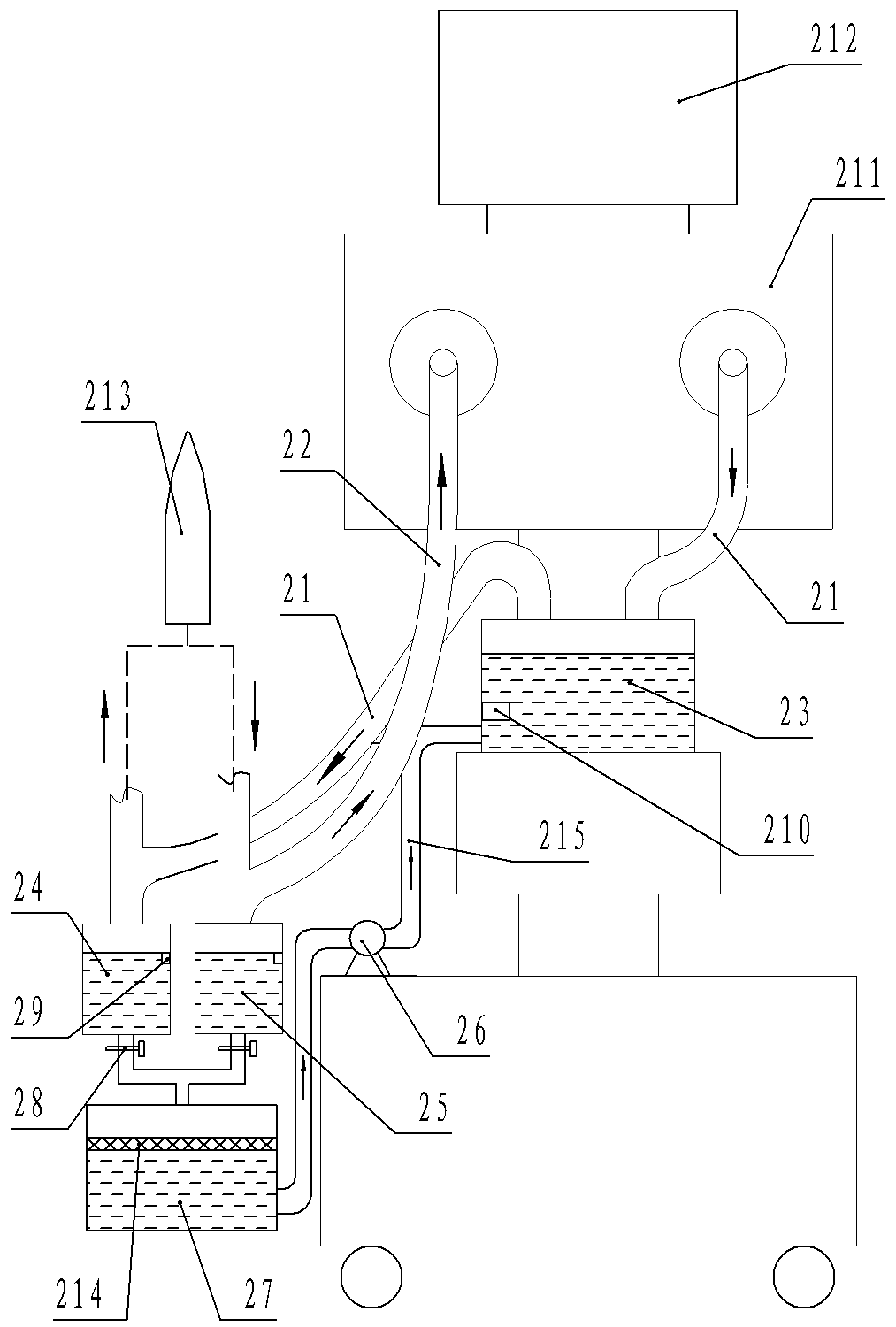
[0024] Such as figure 2 The shown medical ventilator includes an inhalation pipeline 21 and an exhalation pipeline 22 respectively mounted on the control box. The outlet end of the inhalation pipeline 21 and the inlet end of the exhalation pipeline 22 are inserted into the patient's lung The pipe section is connected with the simulated lung 213; the inhalation pipeline 21 is provided with a humidification tank 23 and a first water storage cup 24 in sequence along the direction from the inlet to the outlet of the inhalation pipeline; the exhalation pipeline 22 is provided with a second Water storage cup 25; the height of the water inlet of the first water storage cup 24 is lower than the height of the steam outlet of the humidification tank 23, and the height of the water inlet of the second water storage cup 25 is lower than the height of the outlet end of the exhalation pipeline 22; there is also a The water tank connected to the water inlet of the humidification tank 23 thr...


PUM


Abstract

The invention belongs to the technical field of medical instruments and discloses a medical breathing machine which comprises an inspiration tube and an expiration tube. A humidifying tank and a firstwater accumulation cup are sequentially arranged on the inspiration tube in a direction from an inlet to an outlet of the inspiration tube, and a second water accumulation cup is arranged on the expiration tube. A water tank is communicated with the humidifying tank through a water control part, the first water accumulation cup and the second water accumulation cup are provided with water outletscontrolled by respective water outlet electromagnets, and water level sensors are arranged in the first water accumulation cup and the second water accumulation cup respectively. A humidity sensor isarranged in the humidifying tank, each water level sensor is electrically connected with the corresponding water outlet electromagnet through a control box, and the humidity sensor is electrically connected with the water control part through the control box. By the medical breathing machine, the problem of burning of the respiratory tract of a patient or back-blowing of accumulated water to thelung of the patient due to less water in the humidifying tank or excessive water in the water accumulation cups of an existing medical breathing machine can be solved.

Description

technical field [0001] The invention relates to the technical field of medical devices, in particular to a medical ventilator. Background technique [0002] Medical ventilator is a device that can effectively replace, control or change people's normal physiological breathing, increase lung ventilation, improve respiratory function, reduce respiratory consumption, and save heart reserve. In modern clinical medicine, ventilators have been widely used Respiratory failure caused by various reasons, anesthesia respiratory management during major surgery, respiratory support therapy and emergency resuscitation occupy a very important position in the field of modern medicine. A medical ventilator includes an inhalation pipeline and an exhalation pipeline, and a humidification tank and a first water storage cup are sequentially arranged on the inhalation pipeline along the direction from the inlet to the outlet of the inhalation pipeline; The second water storage cup; the outlet en...

Claims


Application Information

Patent Timeline
Patent Type & Authority Applications(China)
IPC IPC(8): A61M16/00A61M16/16
CPCA61M16/0051A61M16/161A61M16/164A61M2205/18
Inventor 何方杰刘远金兰莫莉李巧覃敏蒋秋媛王玉琴莫翠珍农慧琼张磊熊敏君廖柳莹侯金珍赵丽霞韦凤
Owner LIUZHOU PEOPLES HOSPITAL
Why Eureka
Try Eureka