Positioning device for in-situ windowing of endovascular stent-graft

A stent-graft and positioning device technology, applied in the field of medical devices, can solve problems such as poor long-term effect, poor alignment, difficult operation, etc., to reduce technical requirements and experience dependence, and reduce requirements and experience. Dependence, the effect of reducing personal burden and social burden

Active Publication Date: 2017-01-18
董红霖
View PDF3 Cites 8 Cited by
  • Summary
  • Abstract
  • Description
  • Claims
  • Application Information

AI Technical Summary

Problems solved by technology

[0003] At present, one of the technologies involved in preserving branch arteries is a custom-made stent for patients. The covered stent graft with branch arterial stents is designed and manufactured at the factory. The cycle is long, which takes about three months, and the operation is difficult and the practicability is poor. The other is to open the window of the covered stent before the operation, which needs to be closely combined with the preoperative CT imaging, so that no errors can occur, and after the window is opened, the covered stent needs to be returned to the stent guide sheath. Due to the addition of marking metal rings, etc., it is difficult to retract, and the stent may be damaged after being forced back, and then the stent may be broken and accidentally released after entering the human body, resulting in catastrophic consequences. , it is very likely to cause poor alignment, and then occlusion and stenosis of branch vessels and no alignment at all.

Method used


Image

  • Positioning device for in-situ windowing of endovascular stent-graft
  • Positioning device for in-situ windowing of endovascular stent-graft
  • Positioning device for in-situ windowing of endovascular stent-graft

Examples


Embodiment Construction

[0042] In order to make the objectives, technical solutions, and advantages of the present invention clearer, a description of specific embodiments will be given below in conjunction with the accompanying drawings of the present invention, but not as any limitation to the present invention.

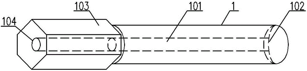
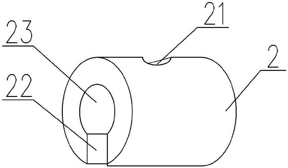
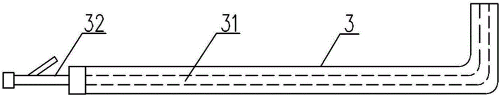
[0043] See Figure 1 to Figure 5 , An in-situ fenestration positioning device for a vascular stent graft, comprising: a pushing member 1, a first through hole 101 is provided on the pushing member 1, a first magnetic attraction member 2 is provided on a first end of the pushing member 1, and a first The magnetic attraction member 2 is provided with a guide wire hole 21 communicating with the first through hole 101, and the second end of the pushing member 1 is provided with a handle 103; the delivery sheath 3, the delivery sheath 3 is provided with a second through hole 31, the delivery sheath The first end of 3 is provided with a second magnetic member 4, the second magnetic member 4 is prov...


PUM


Abstract

The invention relates to a positioning device for in-situ windowing of an endovascular stent-graft. The positioning device comprises a push piece, a conveying sheath and a guiding wire, wherein a first through hole is formed in the push piece, a first magnetic piece is arranged at the first end of the push piece, and a guiding wire hole communicated with the first through hole is formed in the first magnetic piece; a second through hole is formed in the conveying sheath, a second magnetic piece is arranged at the first end of the conveying sheath, a third through hole communicated with the second through hole is formed in the second magnetic piece, and the first magnetic piece is connected with the second magnetic piece in a magnetic attracting manner; and the guiding wire is used for conveying the first magnetic piece and the second magnetic piece. The positioning device provided by the invention has the benefits as follows: after folding of the magnetic pieces, windowing is achieved through guided laser burning punching or a puncture needle method, the step of windowing is simplified, operating difficulty and risks are lowered, the operation time is saved, equipment customization is avoided, and moreover, the operation cost is lowered.

Description

Technical field [0001] The present invention relates to the technical field of medical equipment, in particular to an in-situ fenestration positioning device for a vascular stent graft, in particular to an in-situ fenestration positioning device for aorta and other large arteries. Background technique [0002] With the advent of an aging society and the high incidence of diseases such as smoking and hypertension, there are more and more occurrences of aortic aneurysm-like expansion or dissection. In the past, thoracotomy or laparotomy was necessary, but recently the technology of fenestration with stent graft has been applied , And has been widely recognized by vascular surgery and interventional sciences. Stent graft implantation is currently a very important method for the treatment of large and middle arteries. Although it is expensive, it is still widely used in clinical practice. There are nearly 1 million cases of use worldwide each year, but it faces difficulties in terms ...

Claims


Application Information

Patent Timeline
Patent Type & Authority Applications(China)
IPC IPC(8): A61F2/07
CPCA61F2/07
Inventor 董红霖
Owner 董红霖
Why Eureka
Try Eureka