Method for reducing switch failure between bypass and inverse circuit of uninterrupted power supply

An inverter circuit and bypass technology, applied in battery circuit devices, circuit devices, current collectors, etc., to achieve the effects of simple control, cost reduction, and failure reduction

Inactive Publication Date: 2008-05-21
PANDA ELECTRONICS GROUP +2
View PDF0 Cites 10 Cited by
  • Summary
  • Abstract
  • Description
  • Claims
  • Application Information

AI Technical Summary

Problems solved by technology

[0003] The purpose of the present invention is to invent a method for reducing switching faults between uninterruptible power supply bypass a

Method used


Image

  • Method for reducing switch failure between bypass and inverse circuit of uninterrupted power supply
  • Method for reducing switch failure between bypass and inverse circuit of uninterrupted power supply

Examples


Embodiment Construction

[0014] The present invention will be further described below with reference to the accompanying drawings and embodiments.

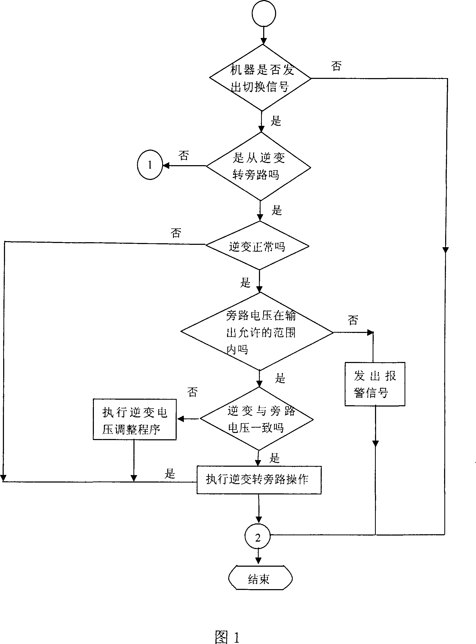
[0015] As shown in Figure 1.

[0016] A method for reducing switching faults between an uninterruptible power supply bypass and an inverter circuit, the steps of which are as follows:

[0017] When the UPS needs to be switched for some reason, first determine the switching direction of the UPS. Whether to switch from inverter to bypass, or from bypass to inverter.

[0018] 1. If the UPS is switching from inverter to bypass, first determine whether the inverter voltage of the UPS is normal.

[0019] (1) If the inverter voltage of the UPS is abnormal, immediately perform the switching operation from inverter to bypass. Jump out of the interrupt.

[0020] (2) If the inverter voltage of the UPS is normal, judge whether the bypass voltage of the UPS is within the allowable output range.

[0021] ①If the bypass voltage is not within the allowable range of ...


PUM


Abstract

The invention discloses a method to reduce switch fault between a bypass of an uninterruptible power supply (UPS) and an inverter circuit, which is characterized in that: a control circuit first judges out the switch mode, either from the bypass to the inverter circuit or from the inverter circuit to the bypass; when a switch is conducted by the UPS; a real and strict synchrony between an invert output and a bypass input is realized while UPS is conducting the switch by utilizing the constantly matured DSP technology, i.e. matching (the same frequency, the same phase and the same amplitude). The invention has the advantages of lowered UPS fault and reduced cost.

Description

technical field [0001] The invention relates to a power supply technology, in particular to a switching method of an uninterruptible power supply, in particular to a method for reducing switching faults between an uninterruptible power supply bypass and an inverter circuit. Background technique [0002] At present, with the continuous progress of information technology and the rapid development of the national economy, more and more departments have put forward higher and higher requirements for the quality of power consumption. . Although with the continuous improvement of the level of electronics, microelectronics, power electronics and communication technologies, the mean time between failures (MTBF) of uninterruptible power supplies has been greatly improved, but in actual operation of uninterruptible power supplies, faults still occur from time to time. For some important departments this is not tolerated. Among the many fault reasons, one of the reasons is very impor...

Claims


Application Information

Patent Timeline
IPC IPC(8): H02J7/00
Inventor 刘少春沈建华
Owner PANDA ELECTRONICS GROUP
Why Eureka
Try Eureka