Control method of constant code rate

A control method and code rate control technology, applied in the direction of pulse modulation TV signal transmission, TV, electrical components, etc., can solve the problems that cannot be applied

Active Publication Date: 2008-05-21
INESA ELECTRON
View PDF0 Cites 11 Cited by
  • Summary
  • Abstract
  • Description
  • Claims
  • Application Information

AI Technical Summary

Problems solved by technology

However, in the latest video standards, such as H.264/MPEG-4 AVC and AVS, due to the adoption of many new

Method used


Image

  • Control method of constant code rate
  • Control method of constant code rate
  • Control method of constant code rate

Examples


Embodiment Construction

[0046] The constant code rate control method of the present invention will be further described in detail below.

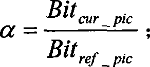
[0047] This embodiment requires encoding and transmission code rate control for an image comprising one I frame, four P frames, and 11 B frames. The image size is 352×288, divided into 16 picture groups (GOP), and the target frame rate is 400Kbps. The present invention provides a constant code rate control method, which is implemented based on adjusting the QB value of the quantization parameter, and the specific implementation steps are as follows:

[0048] Step 1, the video image is continuously divided into several GOPs in time, and the target number of bits of each GOP is recorded as Bit gop , Bit gop = ( 1 + N P + N B ) × ( ...


PUM


Abstract

The invention discloses a control method for constant code rate, which comprises the following steps: the current image is divided into a plurality of image groups; each image group performs image coding by adopting frame-layer code rate control and micro-block layer code rate control. The invention has the advantages of high control precision, small code stream fluctuation, good visual image quality of coding and low calculation complexity, therefore the invention is applicable for coding various software and hardware.

Description

technical field [0001] The invention belongs to the related technical field of digital audio and video transmission control, and in particular relates to a constant code rate control method. Background technique [0002] In real-time video communication, code streams need to be transmitted on networks with different bandwidths. In order to improve the utilization rate of network resources as much as possible while ensuring a relatively high video image quality, there is a demand for the control of the transmission bit rate of the video stream. The current code rate control technology is to control the bit occupancy in the buffer by continuously adjusting the encoding parameters to make it as stable as possible without overflow and underflow; Next, try to ensure the stability of the image quality. In various video compression standards, rate control has always played a very important role, such as: TM5 of MPEG2, TMN8 of H.263, etc. However, in the latest video standards, s...

Claims


Application Information

Patent Timeline
IPC IPC(8): H04N7/26H04N7/24H04N19/176H04N19/177H04N19/61
Inventor 许昌满李国平
Owner INESA ELECTRON
Why Eureka
Try Eureka