Image sensor with a plurality of switchable rows of column amplifiers

a column amplifier and image sensor technology, applied in the field of image sensors, can solve the problems of low location dependence, inconvenient operation, interference or such differences, etc., and achieve the effect of reducing the perception of a stripe pattern or a vertical strip

Active Publication Date: 2013-10-22
ARNOLD & RICHTER CINE TECH GMBH & CO BETRIEBS KG
View PDF24 Cites 2 Cited by
  • Summary
  • Abstract
  • Description
  • Claims
  • Application Information

AI Technical Summary

Benefits of technology

[0020]A dot pattern can therefore be generated instead of a stripe pattern. A “scrambling” of the vertical interference or differences is thus possible. Since the human eye can by no means recognize a dot pattern as easily as a stripe pattern with the same difference of the column amplifiers of the two rows—the recognizability of a dot patterns is approximately only a fifth of the recognizability of a linear pattern—the subjective image quality can be substantially improved. A vertical stripe can also hereby be scrambled.
[0032]If one column line in the image sensor fails due to a defect, it is preferred if the pixel values of the pixels associated with the respective failed column line can be interpolated from the pixel values of respective adjacent pixels. It is in particular therefore preferred if directly mutually following pixels in a respective column of in particular a respective image field block are pairwise alternately connected or connectable to the plurality of column lines. With a color sensor, for example with a Bayer pattern, it can hereby be achieved that, on the failure of a column line, one color (e.g. red or blue) is not missing for the total respective column or for the portion hereof. The interpolation of the pixel values of the failed pixels can hereby be simplified.

Problems solved by technology

Such interference or such a difference is, however, not perceptible to the eye provided it occurs randomly or only pointwise.
If the signal aliasing or signal difference is, however, caused systematically by one of the column amplifiers, the interference or difference occurs in all pixels of the column of the image sensor associated with the respective column amplifier and thus in all picture elements of the corresponding column of the image so that a vertical stripe arises in the image which can be perceived by the eye.
This difference is caused by the fact that the named properties of the column amplifiers are dependent on different influencing variables such as temperature, voltage supply and production tolerances and thus have a relatively high location dependency.

Method used


Image

  • Image sensor with a plurality of switchable rows of column amplifiers
  • Image sensor with a plurality of switchable rows of column amplifiers
  • Image sensor with a plurality of switchable rows of column amplifiers

Examples


Embodiment Construction

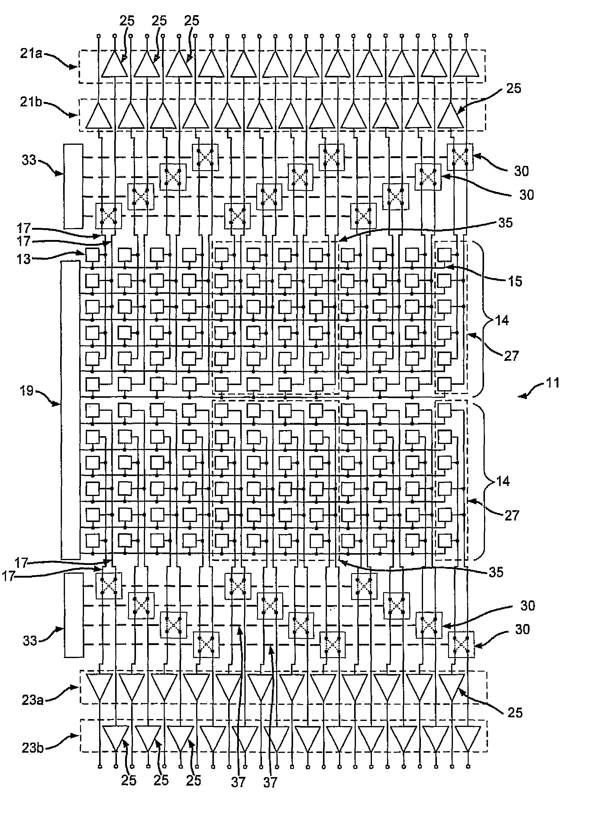
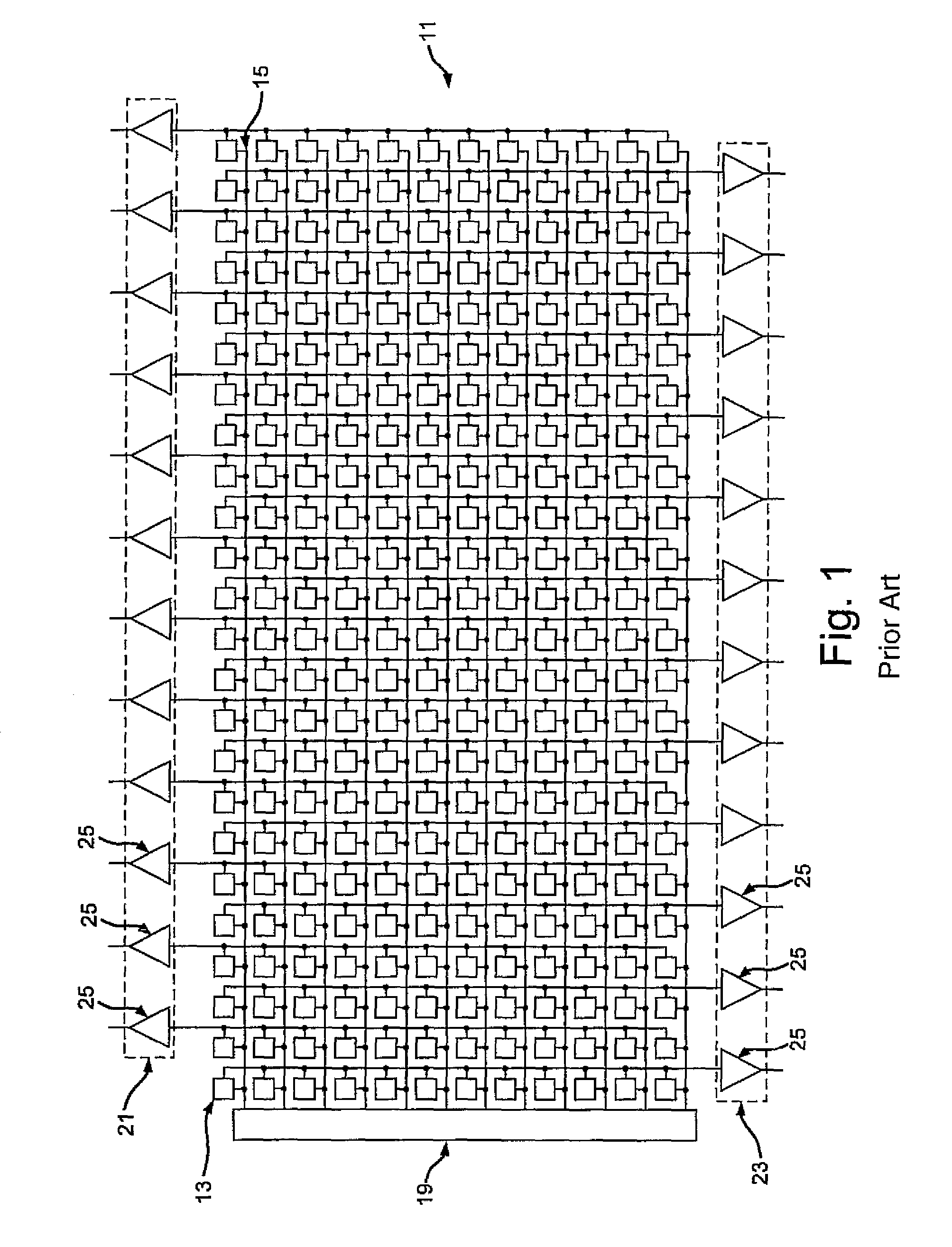
[0046]The image sensor of an electronic motion picture camera shown in FIG. 2 includes an image field 11 which is formed from a plurality of pixels 13 which are arranged along rows and columns. The size of the image field is only selected by way of example. A separate row selection line 15 is provided for each row; a separate column line 17 for each column. The reading out of the image sensor takes place row-wise. For this purpose, the pixels 13 of the respective row are switched by means of the respective row selection line 15 to the respective column lines 17 continuing from the first to the last row. The image field 11 forms an image field block in the sense of the present application. A row addressing logic 19 is provided for addressing the row selection line 15 associated with the respective row to be read out.

[0047]A respective row 21, 23 of column amplifiers 25 is provided above and beneath the image field 11. The first row 21 and the second row 23 each extend parallel to the...


PUM


Abstract

An image sensor for electronic cameras has an image field having at least one image field block which includes a plurality of light sensitive pixels arranged in rows and columns for generating exposure dependent pixel signals, wherein the pixel signals of the pixels of the respective column of the respective image field block can be read out via one or more respective column lines extending parallel to one another. The image sensor has at least one first row of column amplifiers and at least one second row of column amplifiers for the respective image field block. The image sensor is adapted to read out the pixel signals of the pixels of the respective column of the respective image field block of an image or of two mutually following images partly via the at least one first row and partly via the at least one second row of column amplifiers (25).

Description

CROSS-REFERENCE TO RELATED APPLICATIONS[0001]This application claims priority of German Patent Application DE 10 2010 051 438.1 filed Nov. 15, 2010.FIELD OF THE INVENTION[0002]The present invention relates to an image sensor, in particular to a CMOS image sensor, for electronic cameras, in particular electronic motion picture cameras or movie cameras, having an image field, in particular having at least one image field block, in particular two image field blocks, said image field including a plurality of light sensitive pixels arranged in rows and columns for generating exposure dependent pixel signals, wherein the pixel signals of the pixels of the respective column of in particular the respective image field block can be read out via one or more column lines respectively extending parallel to one another. The present invention further relates to a corresponding method.BACKGROUND OF THE INVENTION[0003]In electronic cameras, the light-sensitive elements or pixels convert light incid...

Claims


Application Information

Patent Timeline
Patent Type & Authority Patents(United States)
IPC IPC(8): H04N3/14H04N5/335
CPCH04N5/3658H04N5/3742H04N5/378H04N25/677H04N25/767H04N25/75
Inventor CIESLINSKI, MICHAEL
Owner ARNOLD & RICHTER CINE TECH GMBH & CO BETRIEBS KG
Why Eureka
Try Eureka