Dip angle regulating device

A technology of adjusting device and horizontal direction, applied in measurement device, installation, optics and other directions, can solve the problem of taking a long time and affecting the inclination angle of the scanning head 16, and achieve the effect of improving the swing accuracy

Inactive Publication Date: 2008-05-28
ASIA OPTICAL CO INC
View PDF0 Cites 16 Cited by
  • Summary
  • Abstract
  • Description
  • Claims
  • Application Information

AI Technical Summary

Problems solved by technology

[0007] Because the ball 14 can only rotate around its own center, no matter when the first operating rod 23 or the second operating rod 24 is driven to move, the two legs 221, 222 will simultaneously move along the first horizontal direction X, The second horizontal direction Y swings, causing the inclination angle of the sweeping head 16 to be affected at the same time, and it takes a relatively long time to adjust the sweeping head 16 to the required position.

Method used


Image

  • Dip angle regulating device
  • Dip angle regulating device
  • Dip angle regulating device

Examples


Embodiment Construction

[0030] The aforementioned and other technical contents, features and effects of the tilt angle adjusting device of the present invention will be clearly understood in the following detailed description of a preferred embodiment with reference to the drawings.

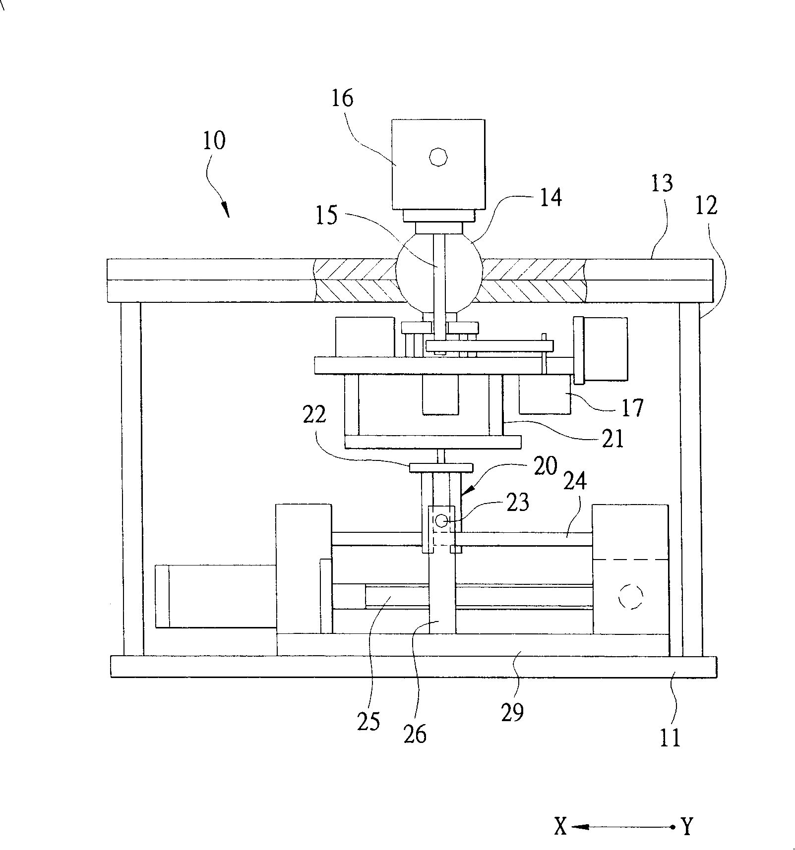
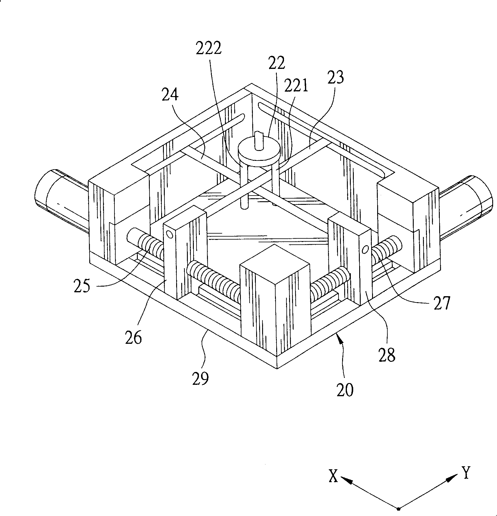
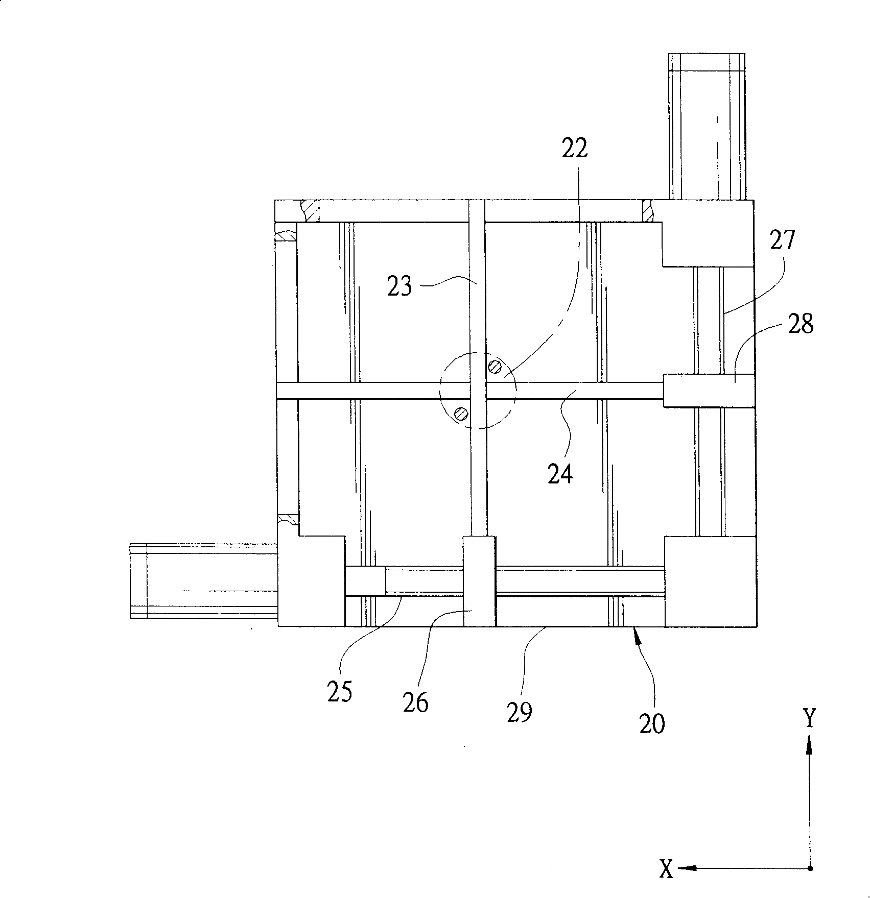
[0031] It should be noted that the relative positional terms used throughout the specification, such as "first horizontal direction X", "second horizontal direction Y", and "vertical direction Z", are based on the directions shown in each figure. And the first horizontal direction X is perpendicular to the second horizontal direction Y and the vertical direction Z.

[0032] Such as Figure 4 , 5 As shown, the preferred embodiment of the inclination adjustment device of the present invention includes a base 30, a first driving unit 40 and a second driving unit 50 fixed on the base 30, and a second driving unit 50 mounted on the second driving unit 40 , 50 and the bearing unit 60 between the base 30 , and a restraining ...


PUM


Abstract

The invention discloses an inclined angel adjusting device. The invention comprises a first driving unit which is fixed on a base, a second driving unit, and a bearing unit which is arranged between the first driving unit and the second driving unit. The first driving unit comprises a first sliding bottom which can be moved reciprocally along a first horizontal direction, the second driving unit comprises a second sliding bottom which can be moved reciprocally along a second horizontal direction, and the bearing unit comprises a bearing plate which can be driven by the first sliding bottom and the second sliding bottom, a connecting rod which is fixed on the bearing plate, a group of rotating components which are connected with the connecting rod, and a group of adapter plates which are used to connect the connecting rod and arrange a balancing target. The invention can adjust undependably inclined angles in the first horizontal direction and the second horizontal direction, and thereby the invention is provided with a property for finishing adjusting work rapidly.

Description

technical field [0001] The invention relates to an angle adjustment device, in particular to an inclination angle adjustment device which enables the adjustment operations of inclination angles in different directions to be independent without interfering with each other. Background technique [0002] Such as figure 1 , 2 , 3, an existing laser level 10 has a bottom block 11, several uprights 12 erected on the bottom block 11, a top block 13 fixed on the uprights 12, and a rotatable A ball 14 installed in an opening of the top block 13, a connecting rod 15 passing through the ball 14, a group of sweeping heads 16 connecting the connecting rod 15, and a driving rod 15 to drive The sweeping head 16 is rotated by a motor 17 . [0003] The ball 14 can be rotated by an angle adjustment unit 20 to change the position of the optical scanning head 16 , so that the optical scanning head 16 can be located at a standard horizontal position. [0004] The angle adjustment unit 20 has...

Claims


Application Information

Patent Timeline
Patent Type & Authority Applications(China)
IPC IPC(8): G02B7/00G01C15/00
Inventor 戚永策
Owner ASIA OPTICAL CO INC
Why Eureka
Try Eureka