LCD device

A liquid crystal display and liquid crystal display panel technology, applied to static indicators, cathode ray tube indicators, instruments, etc., can solve problems such as color shift of liquid crystal displays, and achieve the effect of improving color shift

Inactive Publication Date: 2008-06-04
INNOCOM TECH SHENZHEN +1
View PDF0 Cites 28 Cited by
  • Summary
  • Abstract
  • Description
  • Claims
  • Application Information

AI Technical Summary

Problems solved by technology

[0009] In order to solve the problem of color shift in prior art liquid crystal displays, it is necessary to provide a liquid crystal display that can improve the problem of color shift

Method used


Image

  • LCD device
  • LCD device
  • LCD device

Examples


Embodiment Construction

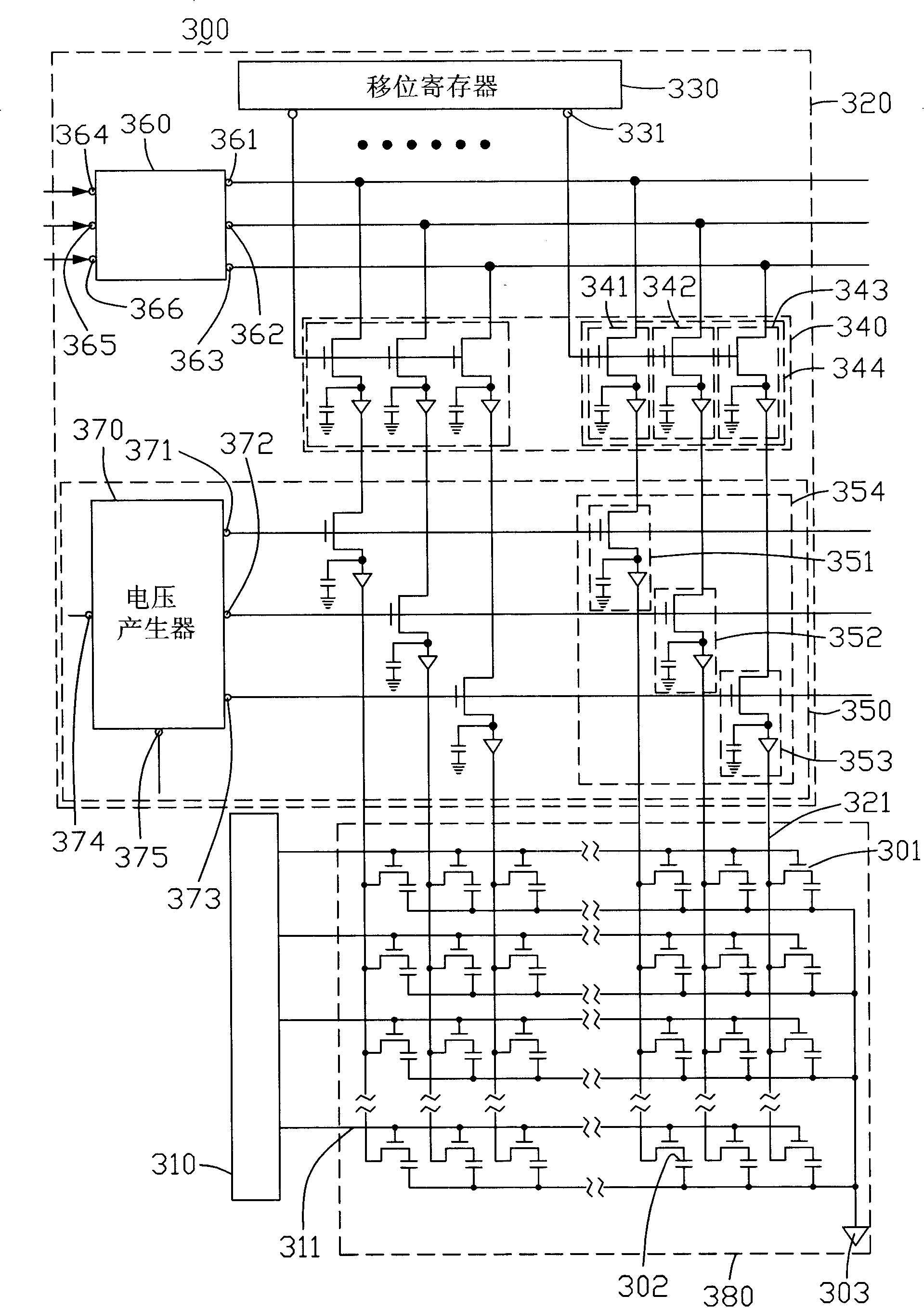
[0015] see image 3 , is a schematic circuit diagram of a preferred embodiment of the liquid crystal display of the present invention. The liquid crystal display 300 includes a scan driving circuit 310 , a data driving circuit 320 and a liquid crystal display panel 380 . The scanning driving circuit 310 is used for scanning the LCD panel 380 , and the data driving circuit 320 is used for providing grayscale voltages for the LCD panel 380 when the LCD panel 380 is scanned.

[0016] The liquid crystal display panel 380 includes a first substrate (not shown), a second substrate (not shown) and a liquid crystal layer (not shown) disposed between the two substrates. The first substrate includes a plurality of scan lines 311 parallel to each other, a plurality of data lines 321 parallel to each other and insulated and perpendicular to the scan lines, a plurality of thin film transistors 301 located at intersections of the scan lines 311 and the data lines 321 and a plurality of a ...


PUM


Abstract

The invention relates to a liquid crystal display, which comprises a liquid crystal display panel, a scanning driving circuit and a data driving circuit. The data driving circuit comprises a shift register, a sampler, a controller and a digital-analog converter and the scanning driving circuit is used for scanning the liquid crystal display panel. The data driving circuit is used for providing a grayscale voltage for the liquid crystal display panel when the liquid crystal display panel is scanned and the controller can respectively adjust the grayscale voltages corresponding to the red, green and blue lights output onto the liquid crystal display panel so as to respectively improve the phenomenon of color shift of the red, green and blue.

Description

technical field [0001] The invention relates to a liquid crystal display. Background technique [0002] Liquid crystal displays have been widely used in modern electronic display devices such as televisions, notebook computers, and personal digital assistants due to their low radiation, low power consumption, and thin thickness. The mixed color light composed of red light, green light and blue light passes through the liquid crystal layer of the liquid crystal display panel to display images on the liquid crystal display panel. Usually, a driving circuit is needed to drive the liquid crystal display panel, and the driving circuit provides the same gray scale voltage for the mixed color light, and the transmittance of red light, green light and blue light is not the same, so there is a certain color light. The phenomenon of partial emphasis, that is, color cast phenomenon. [0003] see figure 1 , is a schematic circuit diagram of a prior art liquid crystal display. The li...

Claims


Application Information

Patent Timeline
Patent Type & Authority Applications(China)
IPC IPC(8): G09G3/36G09G3/20G09G5/02G02F1/133
Inventor 祁小敬李元孟锴
Owner INNOCOM TECH SHENZHEN
Why Eureka
Try Eureka