
Liquid crystal display panel and drive method thereof

A liquid crystal display panel and gate driver technology, applied in the direction of static indicators, nonlinear optics, instruments, etc., can solve the problems of uneven charging of each pixel of the panel, RC delay of data lines, affecting display quality, etc., to reduce discharge time , increase the discharge rate, improve the effect of charging capacity

Inactive Publication Date: 2015-02-04
TCL CHINA STAR OPTOELECTRONICS TECH CO LTD
View PDF7 Cites 19 Cited by
  • Summary
  • Abstract
  • Description
  • Claims
  • Application Information

AI Technical Summary

Problems solved by technology

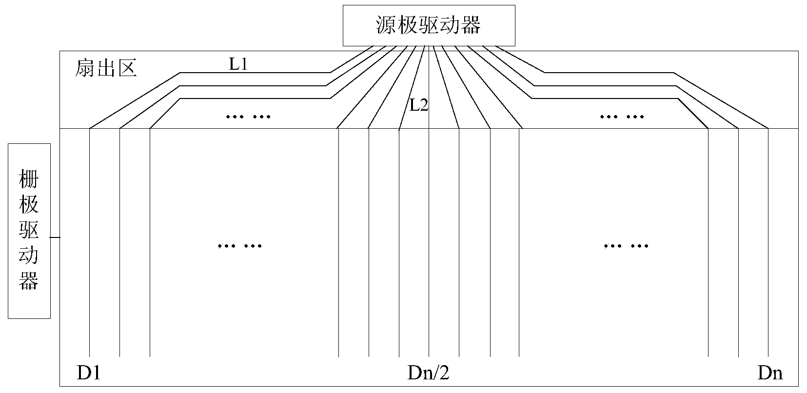
In this way, the larger resistance value of the WOA line will cause serious RC delay when the data line transmits data signals, the charging speed of the pixels at both ends of the LCD panel obviously lags behind the pixels in the middle of the panel, and the charging of each pixel on the panel is uneven. It will cause color shift in the picture displayed on the panel and affect the display quality

Method used


Image

  • Liquid crystal display panel and drive method thereof
  • Liquid crystal display panel and drive method thereof
  • Liquid crystal display panel and drive method thereof

Examples


Embodiment Construction

[0028] In order to make the object, technical solution and advantages of the present invention clearer, the present invention will be further described in detail below in conjunction with the accompanying drawings.

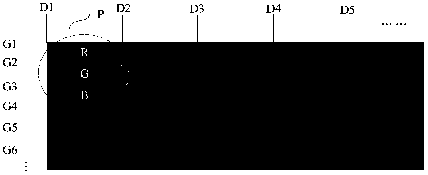
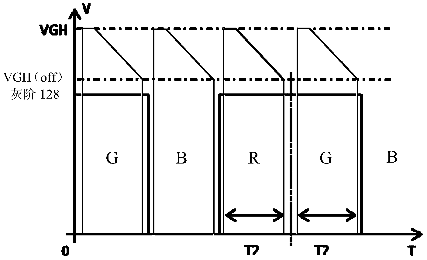
[0029] Figure 3(a) and Figure 3(b) are respectively figure 1 The voltage waveform diagram of the data line Dn / 2 (the data line at the center of the panel) and the data line Dn (the data line at one side of the panel) is shown when the liquid crystal display panel displays a low-gray-scale color mixing picture. Here, a 128-grayscale yellow image is used as an example of a low-grayscale color mixing image, and the grayscale values ​​of the red R, green G, and blue B hue regions are 128, 128, and 0, respectively.

[0030]Please refer to Figure 3(a), VGH represents the gate on-state voltage, VGH(off) represents the voltage at the final closing point of the gate on-state (called the chamfer voltage), which is a special voltage of the gate on-state voltage, Grayscale 1...


PUM


Abstract

The invention discloses a liquid crystal display panel and a drive method thereof, and the liquid crystal display panel comprises a source driver used for offering the data signal; a grid driver used for offering grid signal according to the chamfering voltage; a pixel array electrically connected between the source driver and the grid driver and used for displaying the image according to the data signal and the grid signal; a chamfering circuit electrically connected to the grid driver and used for offering the chamfering voltage, wherein the chamfering circuit is set for reducing the value of the received DC voltage to the voltage value of the chamfering voltage at set time for avoiding flicker and keeping uniformity ratio of illuminance of each region of the liquid crystal display panel.

Description

technical field [0001] The invention relates to the technical field of liquid crystal display, in particular to a liquid crystal display panel and a driving method thereof. Background technique [0002] In order to meet people's requirements for high-speed, high-efficiency, and light and thin products, various electronic components are actively developing towards miniaturization. Various portable electronic devices have gradually become mainstream. For image display panels of portable electronic devices, liquid crystal display panels with superior characteristics such as no radiation have been widely used at present. [0003] Generally, a liquid crystal display panel includes scan lines and data lines, the data lines are driven by a source driver, and the scan lines are driven by a gate driver. Because in the existing large-size liquid crystal panel, the signal line from the source driver to the two ends of the liquid crystal display panel is longer than the signal line fr...

Claims


Application Information

Patent Timeline
Patent Type & Authority Applications(China)
IPC IPC(8): G09G3/36
CPCG09G3/3677G09G3/3688G09G2310/06G09G2310/08G09G2320/0242G09G2320/0247G09G2330/025G02F1/136286G02F1/1368G09G3/3696G09G2300/0452G09G2310/0251G09G2310/027G09G2320/0233
Inventor 曾德康郭东胜
Owner TCL CHINA STAR OPTOELECTRONICS TECH CO LTD
Learn More