

Engine gas-liquid separation device
A gas-liquid separation device and technology of gas-liquid separation, applied in the direction of engine lubrication, engine components, machines/engines, etc., can solve problems such as large-scale engines and complex shapes of crankcases, and achieve the effect of reducing oil consumption
- Summary
- Abstract
- Description
- Claims
- Application Information
AI Technical Summary
Problems solved by technology
Method used
Image

Examples
Embodiment 1
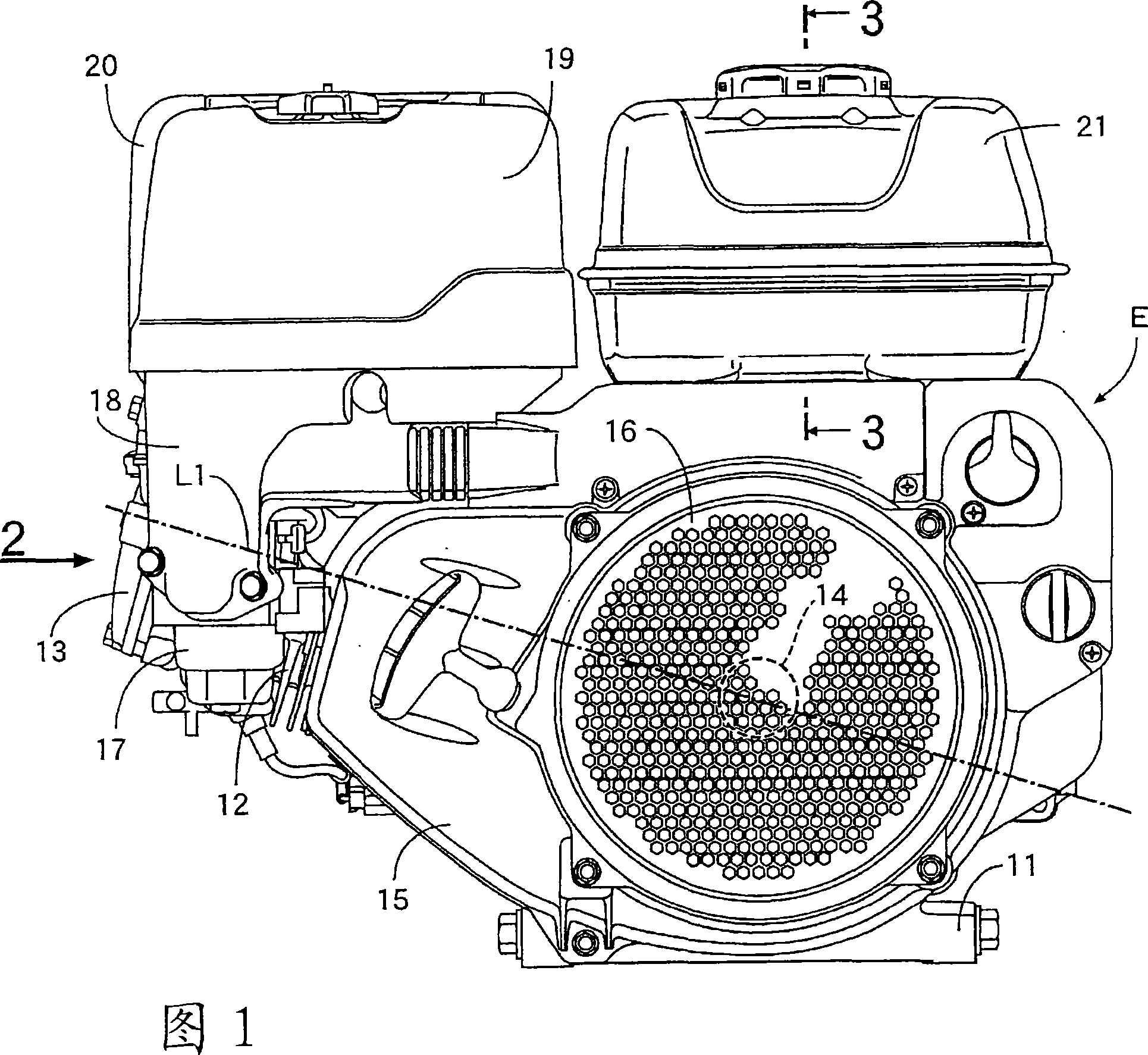
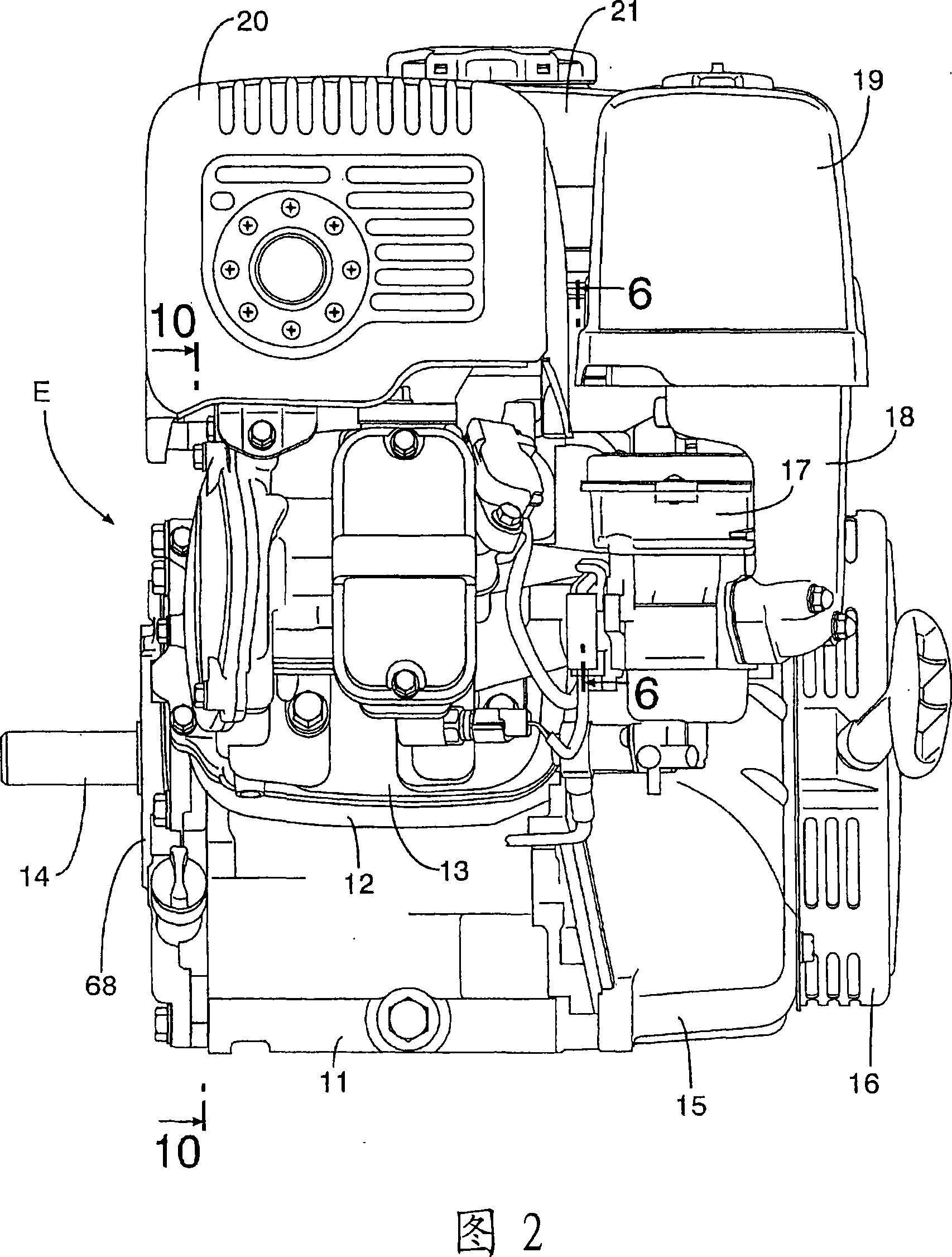
[0076] As shown in FIGS. 1 and 2 , a single-cylinder 4-stroke engine E is arranged such that the cylinder head 12 and the cylinder head cover 13 side are raised relative to the engine case 11 integrally having the crankcase and the cylinder block, so that the cylinder The axis L1 is slightly inclined. The crankshaft 14 protrudes from one end surface of the engine case 11 , and a recoil starter 16 for rotating and starting the crankshaft 14 is provided on an outer surface of a cover 15 covering the other end surface of the engine case 11 . A carburetor 17 is provided on the side of the cylinder head 12 , and an air intake passage 18 extending upward from the carburetor 17 is connected to an air cleaner 19 . On the top of the cylinder head 12 and the cylinder head cover 13, a muffler 20 is installed in parallel with the air cleaner 19, and a fuel tank 21 is installed at a position closer to the crankcase than the air cleaner 19 and the muffler 20. .
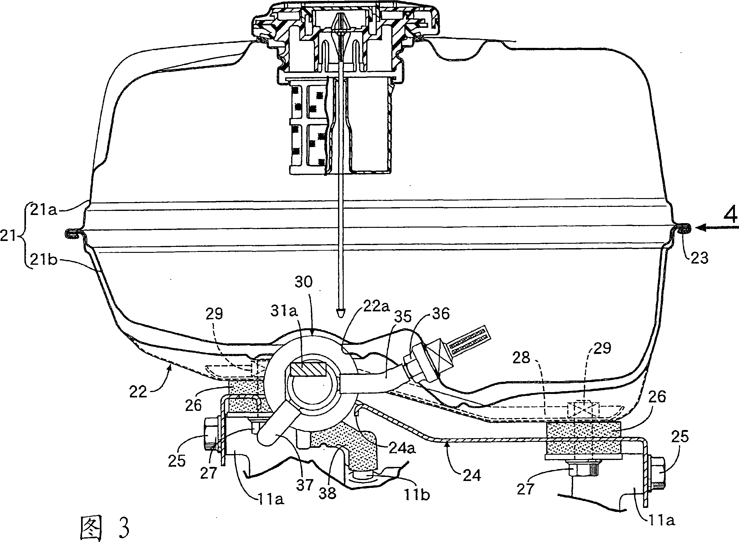
[0077] The fuel tank 21 i...
PUM
 Abstract
Description
Claims
Application Information