Engine gas-liquid separation device
A gas-liquid separation device and technology for gas-liquid separation, which are applied in the directions of engine lubrication, engine components, machines/engines, etc., can solve the problems of complicated crankcase shape and large-scale engine, so as to improve the gas-liquid separation effect and reduce the Oil consumption, effect of shape simplification
- Summary
- Abstract
- Description
- Claims
- Application Information
AI Technical Summary
Problems solved by technology
Method used
Image
Examples
Embodiment 1
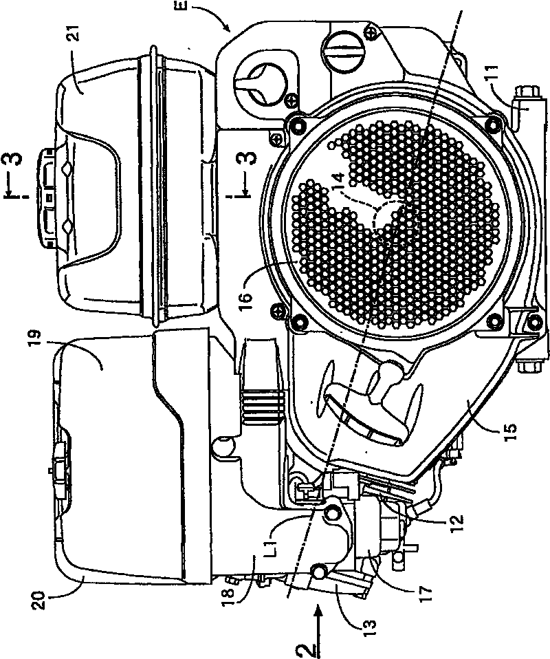
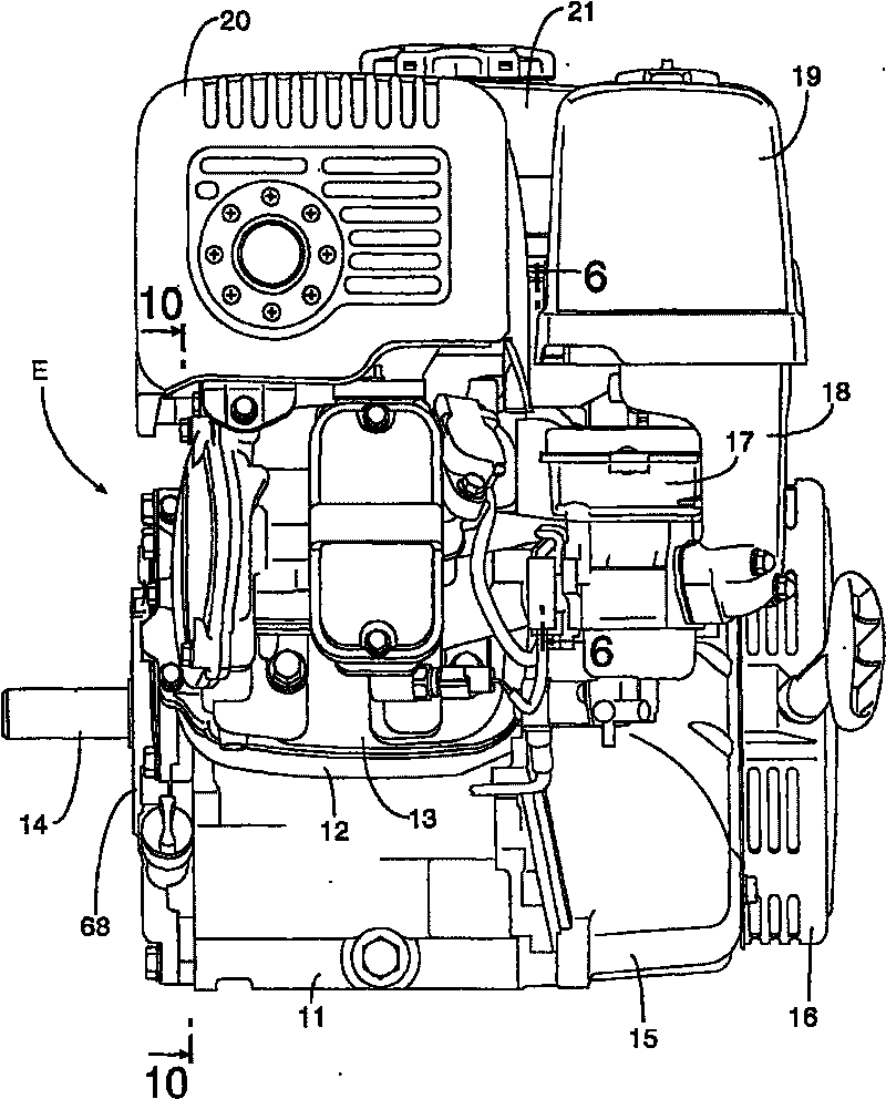
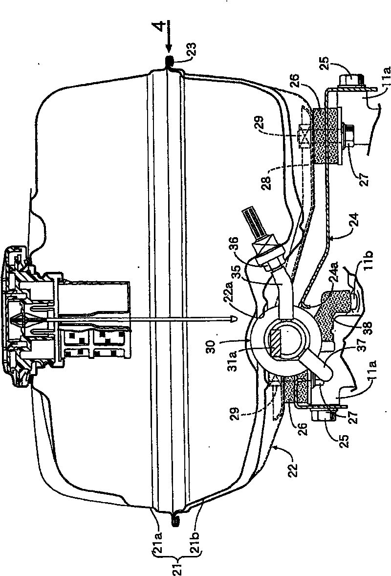
[0071] like figure 1 as well as figure 2 As shown, the single-cylinder 4-stroke engine E is arranged such that the cylinder axis L1 is slightly inclined so that the cylinder head 12 and the cylinder head cover 13 side are raised relative to the engine case 11 integrally having the crankcase and the cylinder block. The crankshaft 14 protrudes from one end surface of the engine case 11 , and a recoil starter 16 for rotating and starting the crankshaft 14 is provided on an outer surface of a cover 15 covering the other end surface of the engine case 11 . A carburetor 17 is provided on the side of the cylinder head 12 , and an air intake passage 18 extending upward from the carburetor 17 is connected to an air cleaner 19 . On the top of the cylinder head 12 and the cylinder head cover 13, a muffler 20 is installed in parallel with the air cleaner 19, and a fuel tank 21 is installed at a position closer to the crankcase than the air cleaner 19 and the muffler 20. .
[0072] The...
PUM
 Abstract
Description
Claims
Application Information
 - R&D
- Intellectual Property
- Life Sciences
- Materials
- Tech Scout
- Unparalleled Data Quality
- Higher Quality Content
- 60% Fewer Hallucinations
Browse by: Latest US Patents, China's latest patents, Technical Efficacy Thesaurus, Application Domain, Technology Topic, Popular Technical Reports.
© 2025 PatSnap. All rights reserved.Legal|Privacy policy|Modern Slavery Act Transparency Statement|Sitemap|About US| Contact US: help@patsnap.com


