
Main unit transmission device for ultra-fine pendulum powder mill

A technology of transmission device and milling machine, which is applied in the direction of transmission device, gear transmission device, mechanical equipment, etc., and can solve the problems of low transmission meshing precision and difficulty in processing bevel gears, etc.

Inactive Publication Date: 2008-06-11
SHANGHAI JIANSHE LUQIAO MASCH CO LTD
View PDF0 Cites 8 Cited by
  • Summary
  • Abstract
  • Description
  • Claims
  • Application Information

AI Technical Summary

Problems solved by technology

Bevel gears are difficult to process and have low meshing precision, especially in high-power pendulum mills.

Method used


Image

  • Main unit transmission device for ultra-fine pendulum powder mill

Examples


Embodiment Construction

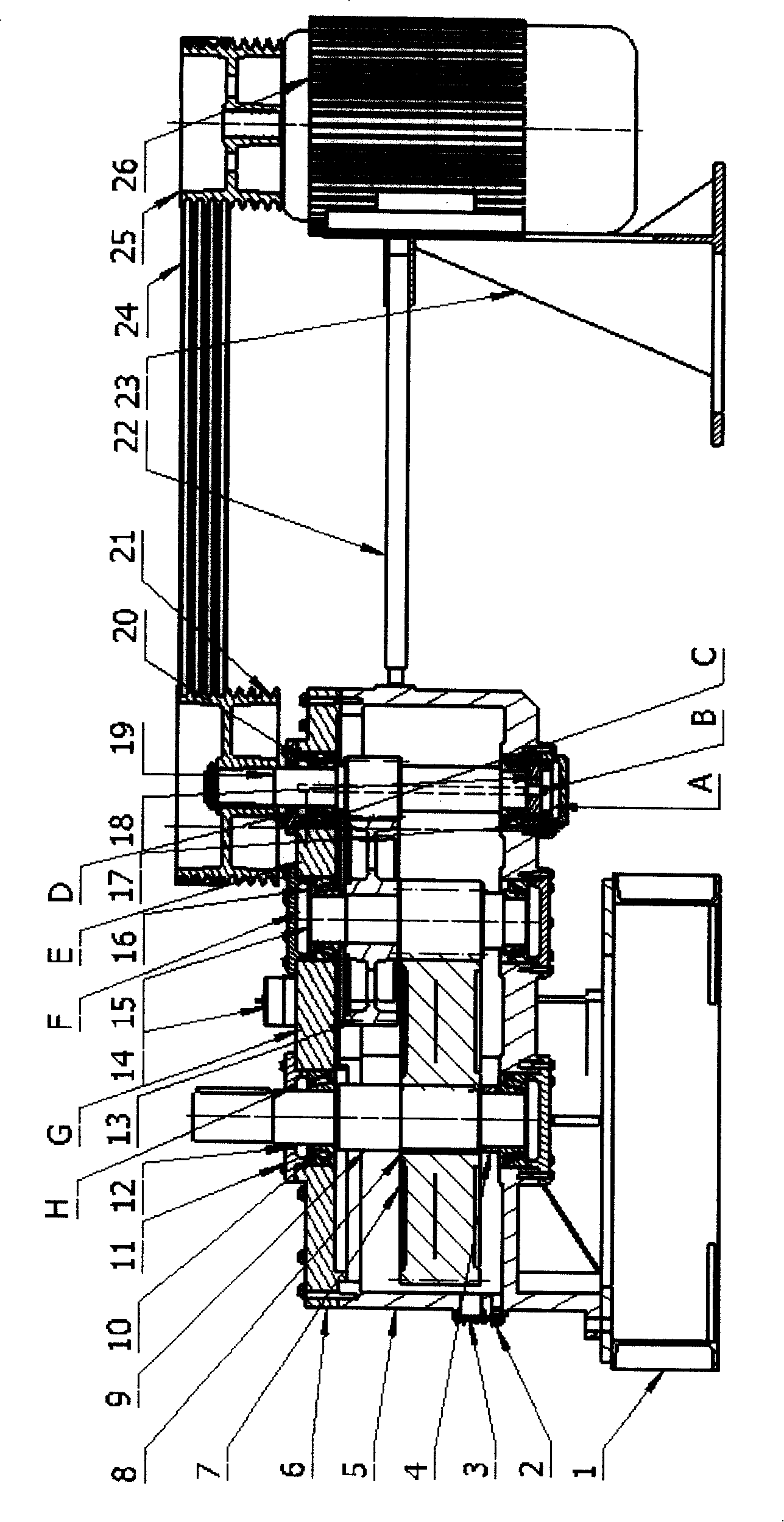
[0008] As shown in the figure, the main engine transmission device used in the ultrafine pendulum mill of the present invention includes a reduction gearbox installed on the gearbox base 1 and a motor 26 installed on the motor mounting base 23 . The motor 26 is a vertical motor, and the motor mount 23 is independently installed on the foundation. The input gear shaft 19 of the reduction box is provided with a reduction box pulley 21, and the motor 26 shaft is provided with a motor pulley 25, and one group of V-belts 24 is connected between the two pulleys 21, 25 to form a V-belt Reduced transmission mechanism. The reduction box is driven by a motor 26 through a V-belt 24 for deceleration transmission.

[0009] A jack bolt 22 for adjusting the tension of the V-belt 24 is arranged between the motor mount 23 and the reduction box.

[0010] Described reduction box is a vertical shaft type reduction box, comprises reduction box body 5, reduction box cover 6, and one to two pairs ...


PUM


Abstract

The invention discloses a driving device for a host machine, which is used for an ultra-fine pendulum type miller. The invention adopts a vertical shaft type reducing box, and one or two cylinder helical gears of horizontal engaging drives which are used to carry out speed reductions are installed inside the reducing box. The invention has simple structure, low cost, stable driving and low noises.

Description

technical field [0001] The invention relates to a pendulum mill for powder processing, in particular to a main drive device of the pendulum mill. Background technique [0002] The main transmission device used in the traditional R-type pendulum mill (Raymond mill) is usually composed of a first-stage belt drive and a first-stage bevel gear drive, or a first-stage bevel gear drive and a pair of cylindrical gear drives. The gear box of this gear box adopts splash oil lubrication method. Bevel gears are difficult to process and have low transmission meshing precision, especially in high-power pendulum mills. Contents of the invention [0003] The technical problem to be solved by the present invention is to provide a main drive device for an ultra-fine pendulum mill, which has a simple structure, low cost, stable transmission and low noise. [0004] In order to solve the above-mentioned technical problems, the main engine transmission device used for the ultrafine pendulum ...

Claims


Application Information

Patent Timeline
IPC IPC(8): B02C15/00F16H1/20F16H57/04
Inventor 吴学峰吴劲松
Owner SHANGHAI JIANSHE LUQIAO MASCH CO LTD
Learn More