Ladder energy dissipater with doped gas device preposed

An energy dissipating and gas device technology, applied in water conservancy projects, marine engineering, coastline protection, etc., can solve the problems of difficult control of aeration amount and aeration concentration, additional gas supply equipment, etc. Air volume is easy to control, easy to optimize the effect

Inactive Publication Date: 2008-06-11
SICHUAN UNIV
0 Cites 31 Cited by

AI-Extracted Technical Summary

Problems solved by technology

Michael Pfister and Willi H. Hager (2006) have studied the form of setting vent holes under the first step before the surface self-aeration reaches the bottom to prote...

Abstract

The invention relates to a stepped energy dissipater, which comprises steps arranged on a bottom slope and an aerating device positioned on the upstream of the steps. The aerating device is provided with four structural forms. In the first structural form, the aerating device is composed of a flip bucket, a vent hole and a vent shaft, in the second structural form, the aerating device is composed of a flip bucket, an aeration slot, a vent hole and a vent shaft, in the third structural form, the aerating device is composed of a flip bucket, a step-down floor, a vent hole and a vent shaft, and in the fourth structural form, the aerating device is composed of a flip bucket, a step-down floor, an aeration slot, a vent hole and a vent shaft. The energy dissipater can not only enhance the stepped energy dissipation rate, but also reduce or avoid the possibility of the cavitation corrosion and the damage to the steps, and thereby effectively solve the problems of the contradiction between the increase of the energy dissipation rate and the improvement of the cavitation corrosion and the damage resistance when an overflow spillway or an overflow dam surface is operated with large discharge per unit width.

Application Domain

Technology Topic

Image

  • Ladder energy dissipater with doped gas device preposed
  • Ladder energy dissipater with doped gas device preposed
  • Ladder energy dissipater with doped gas device preposed

Examples

  • Experimental program(4)

Example Embodiment

[0035] Example 1
[0036] The stepped energy dissipater of the pre-aeration device in this embodiment is used in the power station engineering hub, and the water collection area of ​​the power station is 5317km 2 , The site control catchment area is 5754km 2. The maximum working head of the spillway of the power station is 140m, and the maximum discharge flow is 760m 3 /s, the designed spillway width is 10m, the bottom slope θ is 18°, and the maximum single-width flow is 76m 3 /s.m.
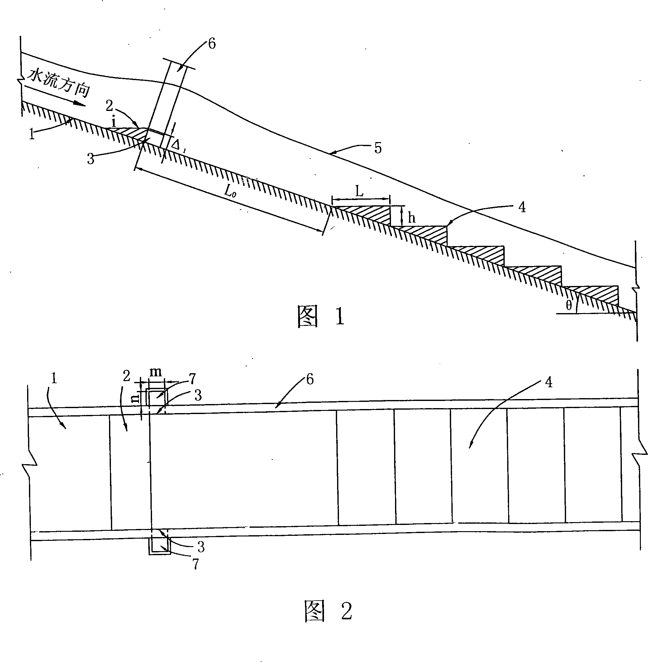
[0037]The structure of the stepped energy dissipater of the pre-aeration device in this embodiment is shown in Fig. 3 and Fig. 4, and includes a step 4 arranged on the bottom slope 1 of the spillway and an aeration device located upstream of the step. The aeration device consists of a sill 2, a vent hole 3 and a gas well 7; the sill 2 is set on the bottom slope 1 of the spillway, and its shape is "wedge", its slope i is 1:5, and its height Δ 1 = 1m, the distance L between its rear end and the front end of the first step in the step 0 =40m; There are two vent holes 3, which are located on the two side walls 6 of the spillway and are close to the rear face of the sill 2, the size of the vent holes is 1.85m×1.5m; there are two vent holes 7, which are located on the outside of the two side walls of the spillway. , The upper end is connected to the atmosphere, and the lower end is connected to the corresponding vent hole. The size of the vent hole is m×n=1.5m×1.5m. The steps 4 fall down h vertically under the original slope, and then are arranged horizontally for a distance L, so that they are alternately arranged, the height of the steps is h=1.5m, and the length L=4.5m.
[0038] Experimental tests show that the energy dissipator in this embodiment can protect the surface of the steps and avoid cavitation damage, and the energy dissipation rate is about 70%.
[0039] The ladder 4 can also adopt a structure that is arranged horizontally for a certain distance L under the original slope, and then vertically dropped h, as shown in Figs. 1 and 2.

Example Embodiment

[0040] Example 2
[0041] The stepped energy dissipater of the pre-aeration device in this embodiment is used for a single-width flow rate of 50-70m 3 /s.m, a hydropower project with a dam surface overflow bottom slope θ of 13°.
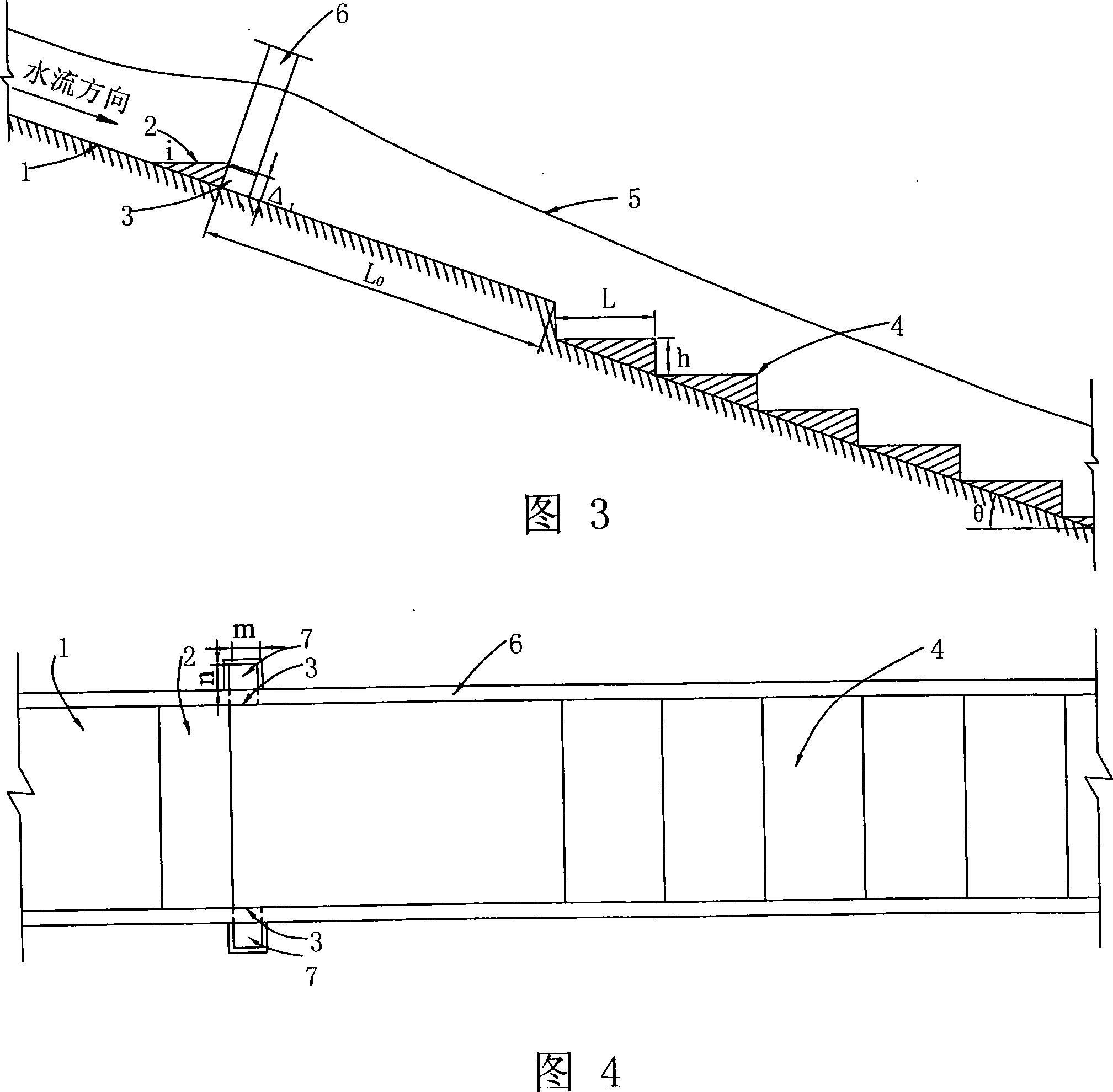
[0042] The structure of the stepped energy dissipater of the pre-aeration device in this embodiment is shown in Figs. 7 and 8, and includes a step 4 arranged on the overflow bottom slope 1 of the dam surface and an aeration device located upstream of the step. The aeration device consists of a sill 2, aeration trough 8, a vent 3 and a gas well 7; the sill 2 is set on the bottom slope 1 where the dam surface overflows, and its shape is "wedge", and its slope i is 1:10, its height Δ 1 =0.5m, the distance L between its rear end and the front end of the first step in the step 0 =42m; the aeration trough 8 is located on the overflow bottom slope of the dam surface and under the sill 2, the trough depth Δ=1.5m, and its range is the area enclosed by a, b, c, and d; there are two ventilation holes 3 , Are located on the overflow walls 6 on both sides of the dam surface and close to the rear end of the sill 2, the size of the ventilation holes is 1.5m×1.5m; there are two ventilation wells 7, which are located on the outside of the overflow walls 6 of the dam surface. The upper end is open to the atmosphere, and the lower end is connected to the corresponding vent hole. The size of the vent hole is m×n=1.5m×1.5m. The steps 4 fall down h vertically under the original slope, and then level a distance L, alternately arranged in this way, the height of the steps is h=2m, and the length L=9m.
[0043] The ladder 4 can also adopt a structure that is arranged horizontally for a certain distance L under the original slope and then vertically dropped h, as shown in Figs. 5 and 6.

Example Embodiment

[0044] Example 3
[0045] The stepped energy dissipater of the pre-aeration device in this embodiment is used for a single-width flow rate of 50-70m 3 /s.m, a hydropower project with a spillway bottom slope θ of 15°.
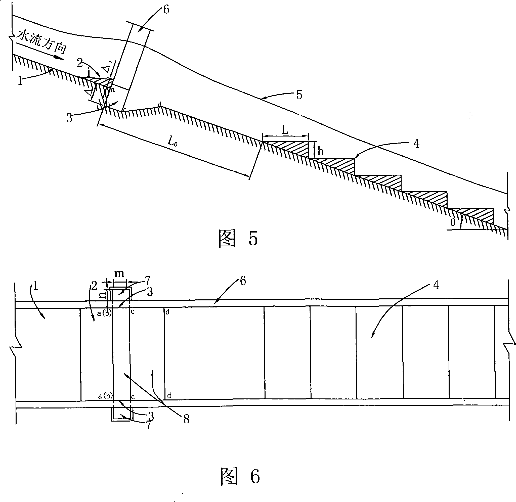
[0046] The structure of the stepped energy dissipater of the pre-aeration device in this embodiment is shown in Fig. 11 and Fig. 12, and includes a step 4 arranged on the bottom slope 1 of the spillway and an aeration device located upstream of the step. The aeration device is composed of a sill 2, a sill 9, a vent hole 3 and a gas well 7; the sill 2 is set on the bottom slope 1 of the spillway, and its shape is "wedge", and its slope i is 1:10, Its height Δ 1 =0.5m, the distance L between its rear end and the front end of the first step in the step 0 =39.78m; slam 9 is located on the bottom slope of the spillway and below slam 2, the slam height Δ 2 =1.5m; There are two vent holes 3, which are located on the two side walls 6 of the spillway and are close to the back end of the sill 2. The size of the vent holes is 1.85m×1.5m; there are two vent holes 7, which are located on both sides of the spillway. On the outside, the upper end is open to the atmosphere, and the lower end is connected to the corresponding vent hole. The size of the vent hole is m×n=1.85m×1.5m. The steps 4 fall down h vertically under the original slope, and then are arranged horizontally for a distance L, so that they are alternately arranged, the height of the steps is h=2m, and the length L=7.5m.
[0047] Experimental tests show that the energy dissipator in this embodiment can make the surface aeration concentration of 5%-9%, can protect the surface of the steps and avoid cavitation damage, and the energy dissipation rate is about 70%.
[0048] The ladder 4 can also adopt a structure that is arranged horizontally for a certain distance L under the original slope, and then vertically dropped h alternately, as shown in Figs. 9 and 10.

PUM

no PUM

Description & Claims & Application Information

We can also present the details of the Description, Claims and Application information to help users get a comprehensive understanding of the technical details of the patent, such as background art, summary of invention, brief description of drawings, description of embodiments, and other original content. On the other hand, users can also determine the specific scope of protection of the technology through the list of claims; as well as understand the changes in the life cycle of the technology with the presentation of the patent timeline. Login to view more.

Similar technology patents

Stress application centrifugal pump with pressurization hole

InactiveCN105626581ASuppress cavitationAvoid cavitation damagePump componentsPumpsCentrifugal pumpEngineering
Owner:TSINGHUA UNIV

Staged flow constraining debris flow drainage slot and application thereof

ActiveCN107806065AEnhanced turbulenceImprove energy dissipation rateDamsArtificial water canalsGeotechnical engineeringMechanical engineering
Owner:INST OF MOUNTAIN HAZARDS & ENVIRONMENT CHINESE ACADEMY OF SCI

Full section ladder energy dissipater

InactiveCN101349048AImprove energy dissipation rateSimple structureBarrages/weirsAdverse effectAirflow
Owner:SICHUAN UNIV

Classification and recommendation of technical efficacy words

  • Avoid cavitation damage
  • Improve energy dissipation rate

Full section ladder energy dissipater

InactiveCN101349048AImprove energy dissipation rateSimple structureBarrages/weirsAdverse effectAirflow
Owner:SICHUAN UNIV

Staged flow constraining debris flow drainage slot and application thereof

ActiveCN107806065AEnhanced turbulenceImprove energy dissipation rateDamsArtificial water canalsGeotechnical engineeringMechanical engineering
Owner:INST OF MOUNTAIN HAZARDS & ENVIRONMENT CHINESE ACADEMY OF SCI
Why Eureka
Try Eureka