Flat-iron and steam generating device thereof

A steam generating device and steam technology, applied in steam generation, steam generation methods, hand irons, etc., can solve the problem that the boiler cannot generate a large amount of steam, and achieve the effects of improving efficiency, increasing vaporization efficiency, and increasing the conduction area

Inactive Publication Date: 2008-06-11
TSANN KUEN CHINA ENTERPRISE
View PDF0 Cites 3 Cited by
  • Summary
  • Abstract
  • Description
  • Claims
  • Application Information

AI Technical Summary

Problems solved by technology

[0004] The invention provides an iron and its steam generating device, which solves the problem that a traditional boiler cannot generate a large amount of steam per unit time, so as to meet the needs of users

Method used


Image

  • Flat-iron and steam generating device thereof
  • Flat-iron and steam generating device thereof
  • Flat-iron and steam generating device thereof

Examples


Embodiment Construction

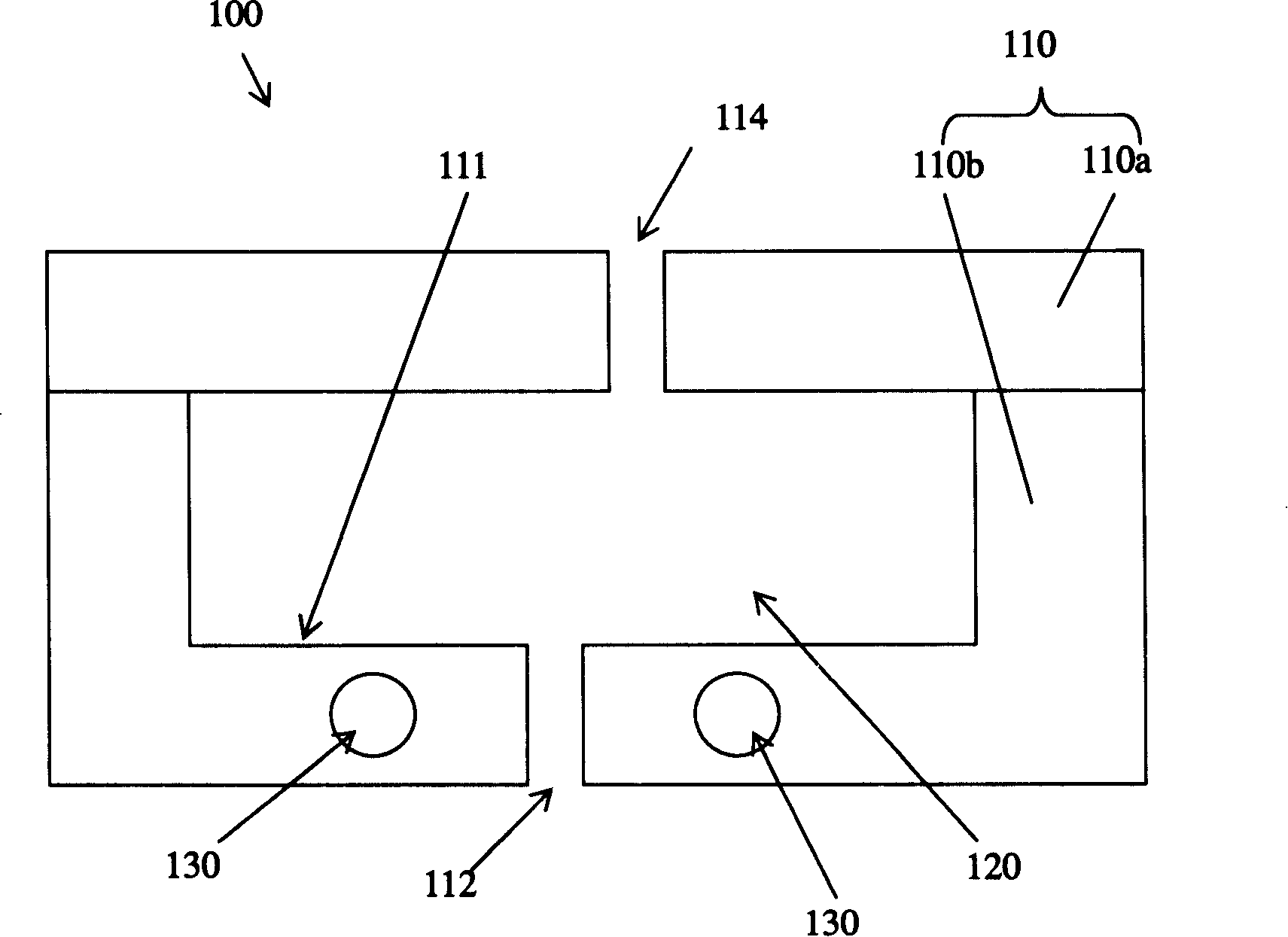
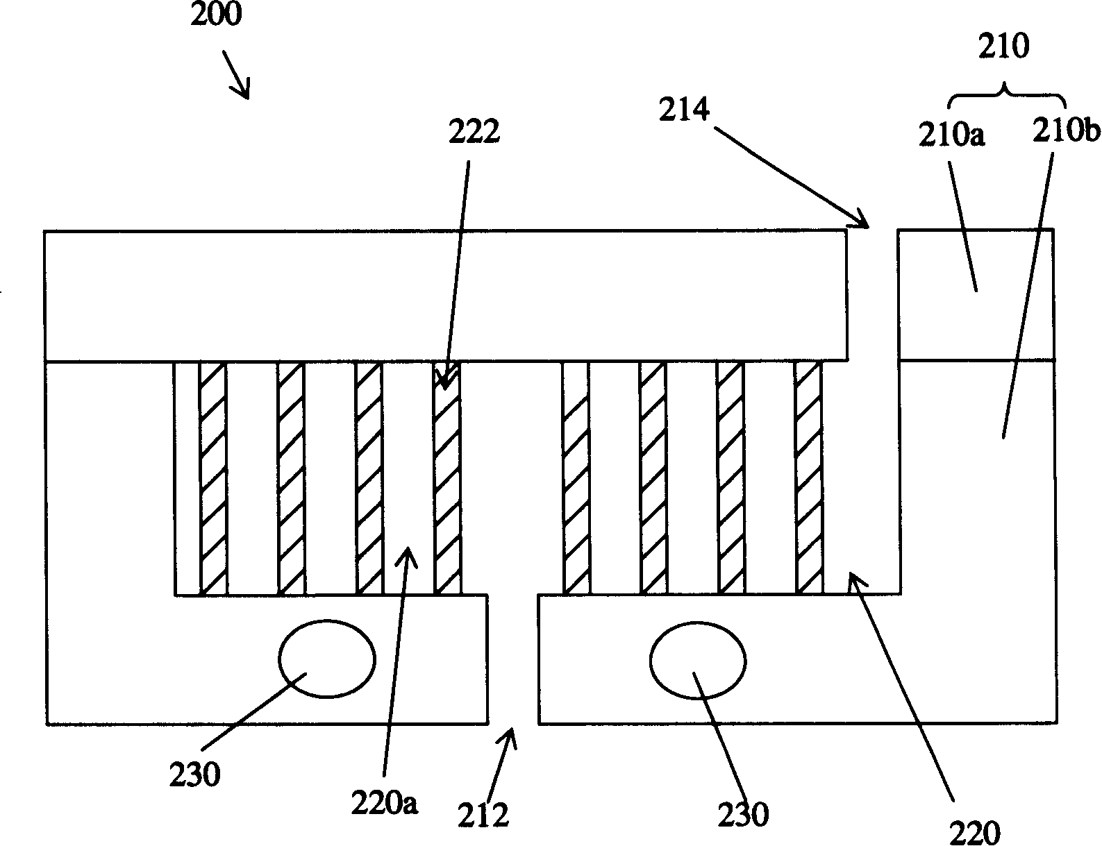
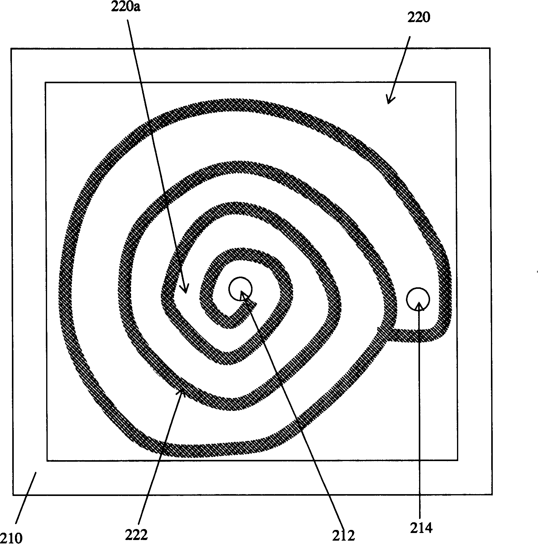
[0034] According to the heat conduction equation, Q=μ×A×ΔT, where Q is the amount of heat conduction, μ is the conduction coefficient of the object, A is the conduction area, and ΔT is the temperature difference, so the heat conduction is mainly related to the conduction coefficient of the object, the size of the conduction area and related to the temperature difference. The present invention mainly provides a steam generating device between the water tank and the electric heating plate, and uses the steam generating device to provide sufficient thermal energy conduction to the water, so that the water can be transformed into superheated and greater than normal pressure before being sent to the electric heating plate. steam. In the present invention, the steam generating device is a pipeline with a heating function, or a boiler with a flow channel structure, that is, the steam generating device of the present invention utilizes the size of the increased conduction area and the...


PUM


Abstract

The invention discloses an electric iron and related steam generating device. The electric iron at least comprises a shell, a water tank, a steam generating device and an electric hot plate; wherein, the water tank is arranged on the shell; the electric hot plate is connected with the shell; the steam generating device is connected with the water tank, which at least comprises a device body and a blank wall; the device body has a steam generating chamber and a shell encircling the steam generating chamber; the blank wall is positioned in the steam generating device for parting the steam generating chamber into a flow channel; wherein, the flow channel is used for increase the conducting area, one end of which is used for communicating with a water inlet of the steam generating chamber and another end of which is used for communicating with an air outlet of the steam generating chamber; the hole diameter of the flow channel is smaller than the section area of the steam generating chamber.

Description

technical field [0001] The invention relates to a steam iron, in particular to a steam iron with a steam generating device with high vaporization efficiency. Background technique [0002] Boiler for conventional steam irons, if attached figure 1 shown, the appended figure 1 It is a schematic cross-sectional view of a conventional boiler 100 applied to a steam iron. The boiler 100 includes a main body 110 composed of an upper shell 110a and a lower shell 110b. The main body 110 has a steam generating chamber 120 inside, an air outlet 114 on the upper shell 110a, and a steam outlet 114 on the lower shell 110b. The water inlet 112, and the electric heating tube 130 is arranged on the lower casing 110b. When water enters the boiler 100 from the water inlet 112 , it will be heated by the electric heating tube 130 to generate steam in the steam generating chamber 120 , and the steam will be directly discharged from the gas outlet 114 immediately to leave the boiler 100 . [00...

Claims


Application Information

Patent Timeline
Patent Type & Authority Applications(China)
IPC IPC(8): F22B1/28F22B27/14D06F75/06
CPCD06F75/10
Inventor 李智华王小伟
Owner TSANN KUEN CHINA ENTERPRISE
Why Eureka
Try Eureka