Device and method for treating power plant waste water

A power plant wastewater and treatment device technology, applied in the direction of gaseous effluent wastewater treatment, water/sewage treatment, heating water/sewage treatment, etc., can solve the problem of increasing investment costs and operating costs, short flue lengths, and relatively large impact on unit loads Large and other problems, to achieve the effect of improving the efficiency of wastewater treatment and reducing the amount of steam

Pending Publication Date: 2018-09-21
北京北科欧远科技有限公司
View PDF8 Cites 3 Cited by
  • Summary
  • Abstract
  • Description
  • Claims
  • Application Information

AI Technical Summary

Problems solved by technology

[0002] Although the wet desulfurization process in the prior art can solve the basic technical problems of electric field wastewater treatment, the operation steps are too complicated, and the treatment process requires a lot of manpower and material resources, resulting in high sewage treatment costs, which cannot be ignored in thermal power operation management. economic burden
[0003] Chinese patent CN 106167283A provides a coal-fired power plant desulfurization wastewater flue spray evaporation zero-emission treatment device and method, including hot flue gas distribution components, desulfurization wastewater atomization components and hot secondary air injection components, through which the desulfurization The salt in the wastewater is crystallized and dried to achieve zero discharge of desulfurization wastewater under high load and simultaneously remove Hg in the flue gas; The temperature is low; for renovation projects or projects with low-temperature economizer installed, due to the short length of the available flue, the evaporation is not complete, which will further lead to dust accumulation and corrosion
Chinese patent CN 107089755A provides a zero-discharge system device for desulfurization wastewater evaporated by a drying tower after concentration, including a pretreatment unit, a membrane concentration unit, and an air preheater bypass drying unit, through which the desulfurization wastewater is evaporated to achieve wastewater Zero emission, but due to the use of a membrane concentration unit in this process, the system is complex and the investment cost is high, and the reverse osmosis membrane used needs to be replaced regularly, and the operating cost is high; at the same time, it is required to set up a pretreatment unit before the membrane concentration, which further increases the cost. Investment cost and operating cost, poor economy, and will generate new waste sludge, difficult to promote
However, since the fine solid particles or salts evaporated from the crystallization tower of this process enter the fly ash, heavy metals and chloride ions in the desulfurization wastewater migrate into the fly ash, which will affect the comprehensive utilization of fly ash in power plants. Power plants with strict standards are not suitable

Method used


Image

  • Device and method for treating power plant waste water
  • Device and method for treating power plant waste water
  • Device and method for treating power plant waste water

Examples


Embodiment 1

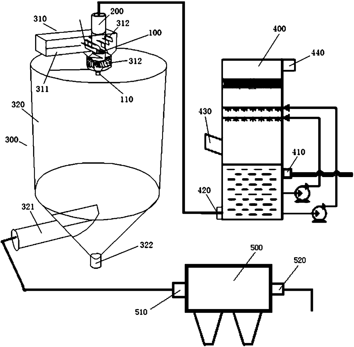
[0046] Such as figure 2 As shown, the present invention provides a plant wastewater treatment device, including: rotary atomizer 100, evaporation tower dust collector 500 and concentration tower 400; also includes: atomization evaporation tower 300; described atomization evaporation tower 300 is provided with heat Air distributor 310 and evaporation tower tank body 320; The bottom of described evaporation tower tank body 320 is provided with air outlet 321 and ash outlet 322; Described hot air distributor 310 is arranged on the top of described evaporation tower tank body 320 or The side wall of the upper end of the evaporation tower tank body 320; the hot air distributor 310 includes an air duct 311 and a hot air deflector 312 arranged in the air duct 311; the outlet of the air duct 311 is connected to the The inner cavity of the evaporation tower tank body 320 is connected; the air duct of the hot air distributor 310 is provided with a rotary atomizer installation sleeve 20...

Embodiment 2

[0056] Such as Figure 5 As shown, this embodiment is based on Embodiment 1, the hot air deflector 312 includes: an air turbulence deflector 3121 and an air swirl deflector 3122; the air turbulence deflector 3121 is Relative to the air flow direction, the air duct is arranged in a leaf mosaic manner; the air swirl deflector 3122 is fixedly arranged on the outer wall of the rotary atomizer installation sleeve 200, arranged in a fan blade structure .

[0057] The setting of the air turbulence deflector is used to block the air velocity and change the flow state of the air in the air duct to a turbulent state, which helps to achieve the uniform filling of the air duct and the formation of a relatively uniform high temperature that meets the conditions of evaporation and vaporization field; the setting of the air swirl deflector helps to transform the turbulent air into a swirl, which in turn helps the high-temperature flue gas to pass through the tube wall of the rotary atomizer...

Embodiment 3

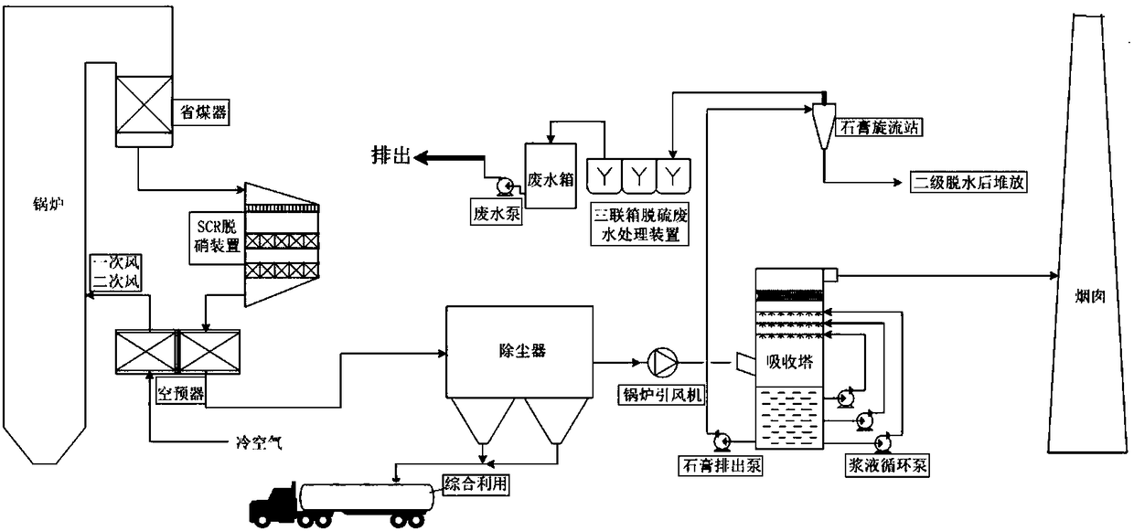
[0063] On the basis of the above embodiments, this embodiment also provides a power plant wastewater treatment method, using the aforementioned power plant wastewater treatment device, the power plant is provided with a denitrification device, a waste water tank, a dust collector, a boiler induced draft fan and an absorption Tower, said method comprises the steps:

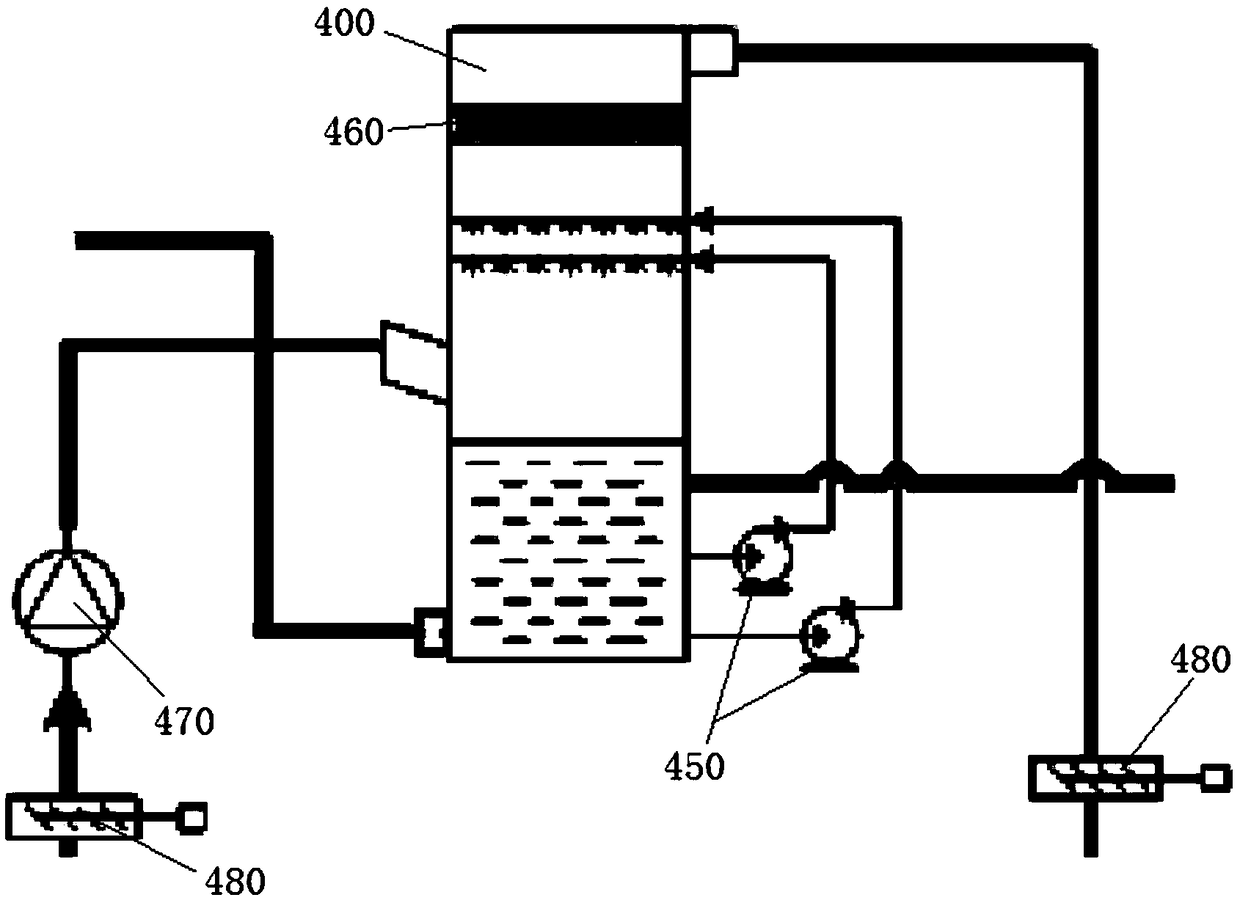
[0064] The waste water input interface of described thickening tower is established to be connected with the waste water tank that is provided with in the power plant through the first water delivery pipeline, and the setting of described first water delivery pipeline satisfies that waste water is led to described thickening tower from described waste water tank;

[0065] The rotary atomizer installation sleeve is established to be connected with the concentrated water output interface through the second water delivery pipeline, and the setting of the second water delivery pipeline meets the requirement that the con...


PUM


Abstract

The invention provides a device for treating power plant waste water, aiming at solving the technical problem of how to achieve zero emission of the power plant waste water. The device has a structurecomprising a rotary atomizer, an evaporation tower deduster, a concentrating tower and an atomizing evaporation tower; the atomizing evaporation tower is provided with a hot air distributor and an evaporation tower tank; the hot air distributor comprises an air flue and a hot air guide plate; an outlet of the air flue is communicated with an inner cavity of the evaporation tower tank; the air flue of the hot air distributor is internally provided with a rotary atomizer mounting sleeve, and the rotary atomizer mounting sleeve is internally provided with the rotary atomizer; the concentrating tower is provided with a waste water input interface, a concentrated water output interface, a concentrated flue gas inlet and a concentrated flue gas outlet; the concentrated water output interface isconnected with the rotary atomizer in a sealing way by means of a pipeline; the concentrated flue gas inlet and the concentrated flue gas outlet are connected with a power plant flue gas discharge pipeline; the evaporation tower deduster is provided with a dedusting interface and a dust-free air discharge hole; an air outlet is connected with the dedusting interface. The device has the technicaladvantage of realizing zero emission of the power plant waste water.

Description

technical field [0001] The invention relates to the technical field of flue gas desulfurization wastewater treatment, in particular to a power plant wastewater treatment device and method. Background technique [0002] Although the wet desulfurization process in the prior art can solve the basic technical problems of electric field wastewater treatment, the operation steps are too complicated, and the treatment process requires a lot of manpower and material resources, resulting in high sewage treatment costs, which cannot be ignored in thermal power operation management. economic burden. [0003] Chinese patent CN 106167283A provides a coal-fired power plant desulfurization wastewater flue spray evaporation zero-emission treatment device and method, including hot flue gas distribution components, desulfurization wastewater atomization components and hot secondary air injection components, through which the desulfurization The salt in the wastewater is crystallized and drie...

Claims


Application Information

Patent Timeline
Patent Type & Authority Applications(China)
IPC IPC(8): C02F1/04C02F1/16C02F103/18
CPCC02F1/04C02F1/16C02F2103/18
Inventor 孙昕员在斌吴占琪
Owner 北京北科欧远科技有限公司
Why Eureka
Try Eureka