

Flicker demodulation method
A technology of voltage flicker and detection method, which is applied in the direction of using digital measurement technology for measurement, amplitude modulation oscillation demodulation components, etc., can solve the problems of complex and unsuitable algorithms, and achieve the effect of small calculation amount and accurate measurement.
Inactive Publication Date: 2008-06-11
HEILONGJIANG UNIV +1
View PDF0 Cites 9 Cited by
- Summary
- Abstract
- Description
- Claims
- Application Information
AI Technical Summary
Problems solved by technology
The purpose of the present invention is to overcome the problems that the existing detection method is easily affected by the fundamental voltage and fundamental frequency, and it is necessary to design a low-pass filter or a band-pass filter, the algorithm is relatively complicated, and it is not suitable for application in digital measuring devices. And then propose a kind of voltage flicker detection method, the step of the inventive method is:
Method used
View moreImage
Smart ImageViewing Examples

Examples
specific Embodiment approach 1
Login to View More PUM
 Abstract
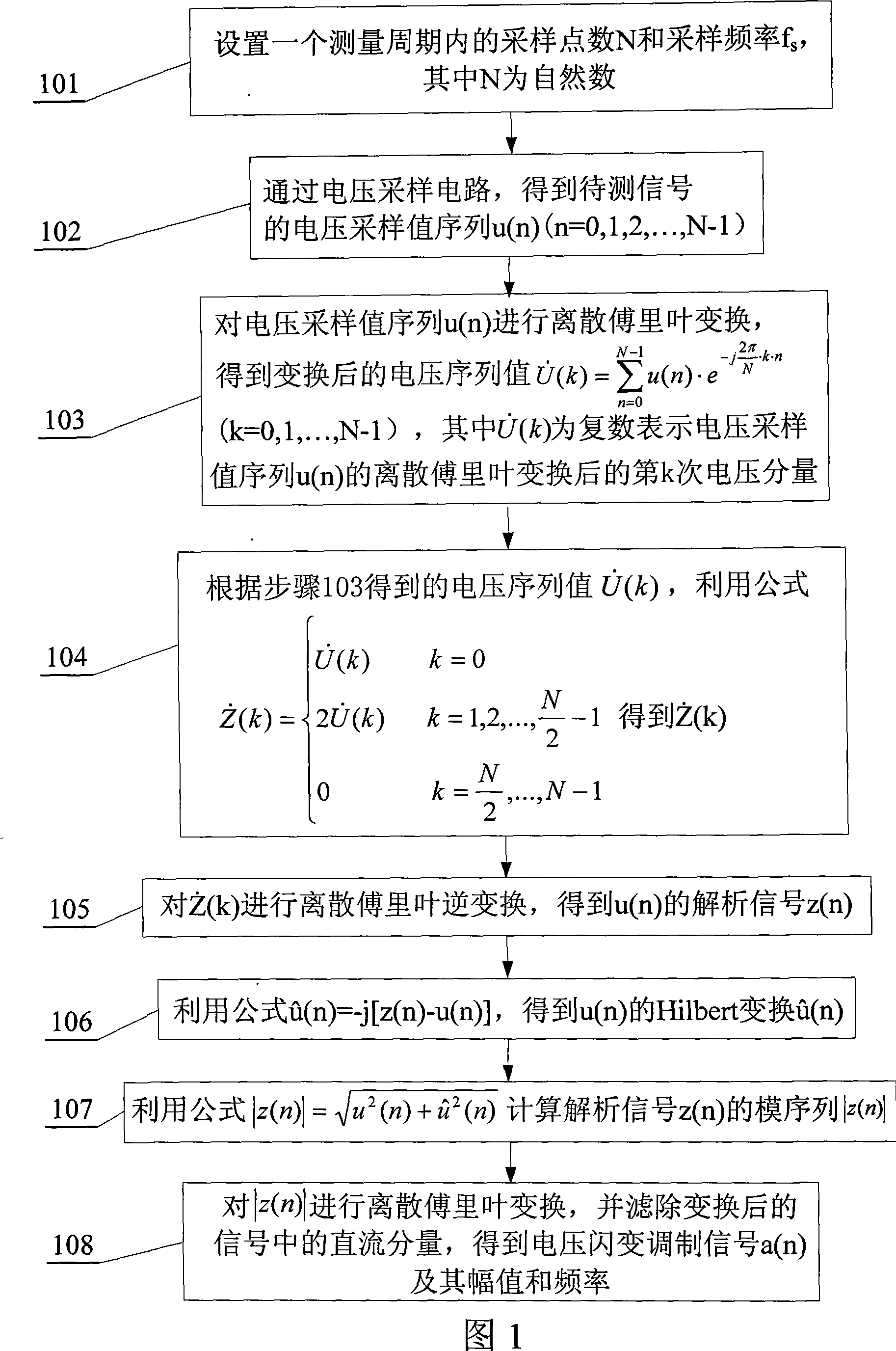
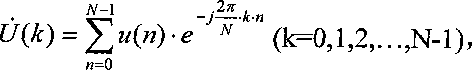
A voltage flicker demodulation method is provided, which relates to a method for demodulating voltage flicker modulation wave. The invention can solve the problems that: the existing demodulation method is easily affected by fundamental voltage and fundamental frequency, additional filter needs to be designed, the arithmetic is complex and is not suitable to use in digital measurement device. The steps of the method in the invention are that: step 101 is to set the number of points sampled N and sampling frequency fs; step 102 is to get voltage sampling value serial u(n) through voltage sample circuit; step 103 is to get voltage successive value Z(k) by discrete Fourier transform of u(n); step 104 is to calculate U(k) according to voltage successive value; step 105 is to get analytic signal z(n) of u(n) by discrete Fourier transform of Z(k); step 106 is to calculate Hilbert of u(n) and transform u(n); step 107 is to calculate the module sequence |z(n)| of z(n) with the formula of |z(n)|=u< 2 >(n)+u< 2 >(n); step 108 is to have discrete Fourier transform to |z(n)|, filter direct-current component and get voltage flicker modulation signal a(n) and the amplitude and frequency.
Description
Technical field: The invention relates to a detection method of a voltage flicker modulated wave, belonging to the technical field of detection of a voltage flicker signal. Background technique: The voltage flicker signal is an amplitude-modulated wave with power frequency voltage as the carrier. There are three commonly used detection methods for the flicker modulated wave: half-wave effective value method, square demodulation method and full-wave rectification method. The effect of the half-wave RMS method is general, and it is easily affected by the fundamental voltage and frequency; both the square demodulation method and the full-wave rectification method need to design a low-pass filter or a band-pass filter with strict requirements on the frequency band. In order to properly filter the DC, power frequency and power frequency harmonics, the filtering algorithm is also relatively complicated. Therefore, these three methods are not suitable for application in digital m...
Claims
Login to View More Application Information
Patent Timeline
 IPC IPC(8): G01R19/25H03D1/04
Inventor张东中佟为明郑艳明时文东李中伟宋雪雷袁帅
OwnerHEILONGJIANG UNIV