
Synchronization controller for wheel pair speed of engine static-state test platform

A synchronous control and mechanical synchronization technology, which is applied to controllers with specific characteristics, electric controllers, and comprehensive factory control, etc., can solve problems such as no automatic control of synchronous rotating devices, failure to meet production requirements, and lack of adjustment accuracy. To achieve the effect of comprehensive functions, convenient maintenance and good followability

Inactive Publication Date: 2008-06-18
CRRC BEIJING ERQI LOCOMOTIVE CO LTD
View PDF0 Cites 5 Cited by
  • Summary
  • Abstract
  • Description
  • Claims
  • Application Information

AI Technical Summary

Problems solved by technology

[0003] At present, in the locomotive traction test, there is no device that automatically controls the synchronous rotation of each wheel pair, and the synchronization of the wheel pairs can only be adjusted manually by adjusting the resistance of each wheel pair to the axle.
Manual adjustment has poor followability, large error, and lack of adjustment accuracy. The error can only be controlled within 3%, which cannot meet the production requirements.

Method used


Image

  • Synchronization controller for wheel pair speed of engine static-state test platform
  • Synchronization controller for wheel pair speed of engine static-state test platform
  • Synchronization controller for wheel pair speed of engine static-state test platform

Examples


Embodiment Construction

[0020] The present invention will be described in detail below according to the embodiments of the present invention and in conjunction with the accompanying drawings.

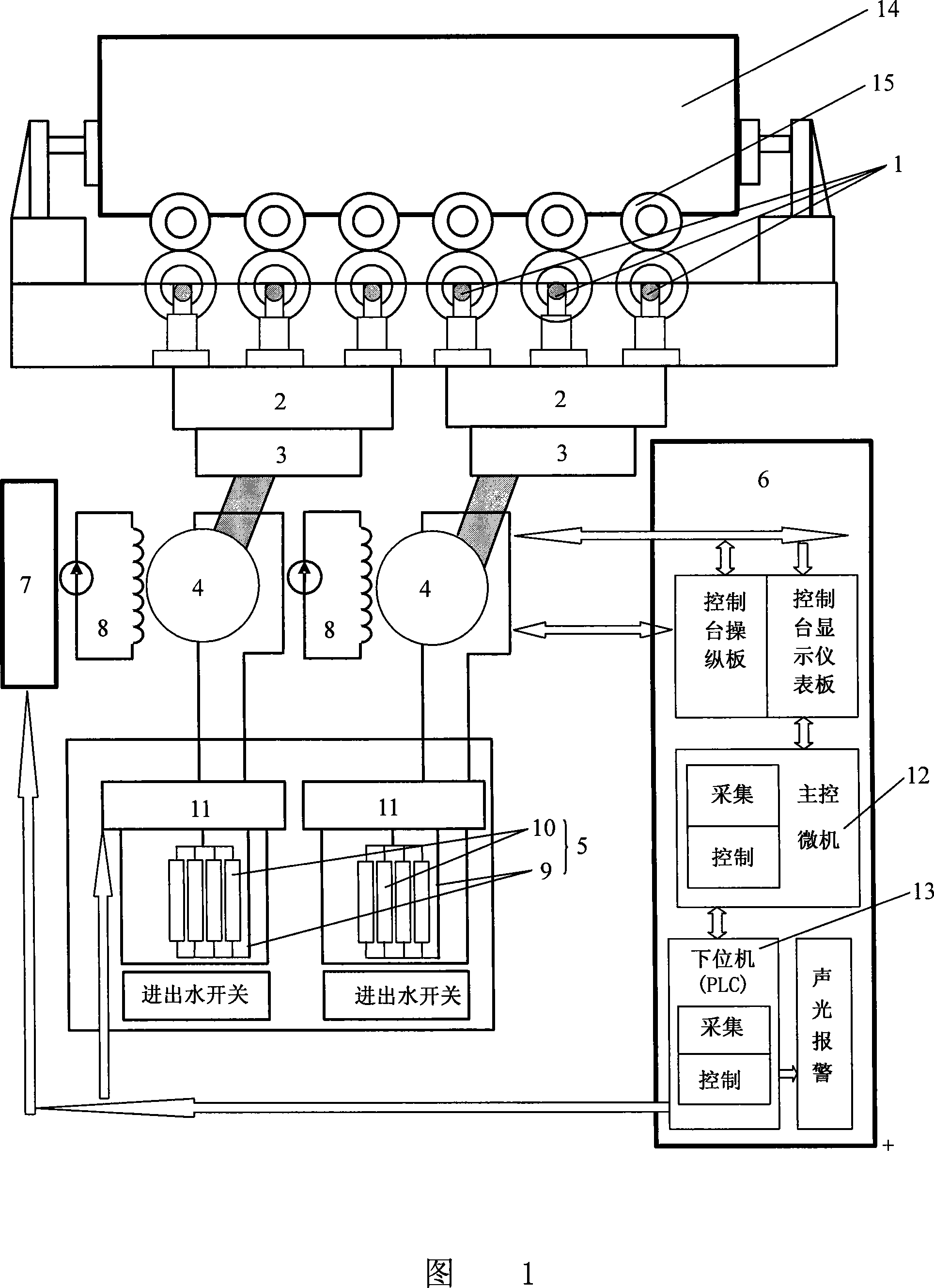
[0021] As shown in Fig. 1, the present invention includes six pairs of oppositely arranged axles 1, and every three pairs of axles 1 are connected into a mechanical synchronous system 2, and each mechanical synchronous system 2 is respectively connected with a transmission system 3, and the two transmission systems 3 are respectively connected with a measurement The dynamometer 4 and the second dynamometer 4 are connected to a load 5 respectively. The synchronous control system 6 is connected with the second dynamometer 4 and the second load 5 , and is connected with an excitation controller 7 that controls the rotation speed of the dynamometer 4 .

[0022] Each mechanical synchronization system 2 includes three pairs of wheel shafts 1, one pair of wheel shafts corresponds to a pair of track wheels, and each w...


PUM


Abstract

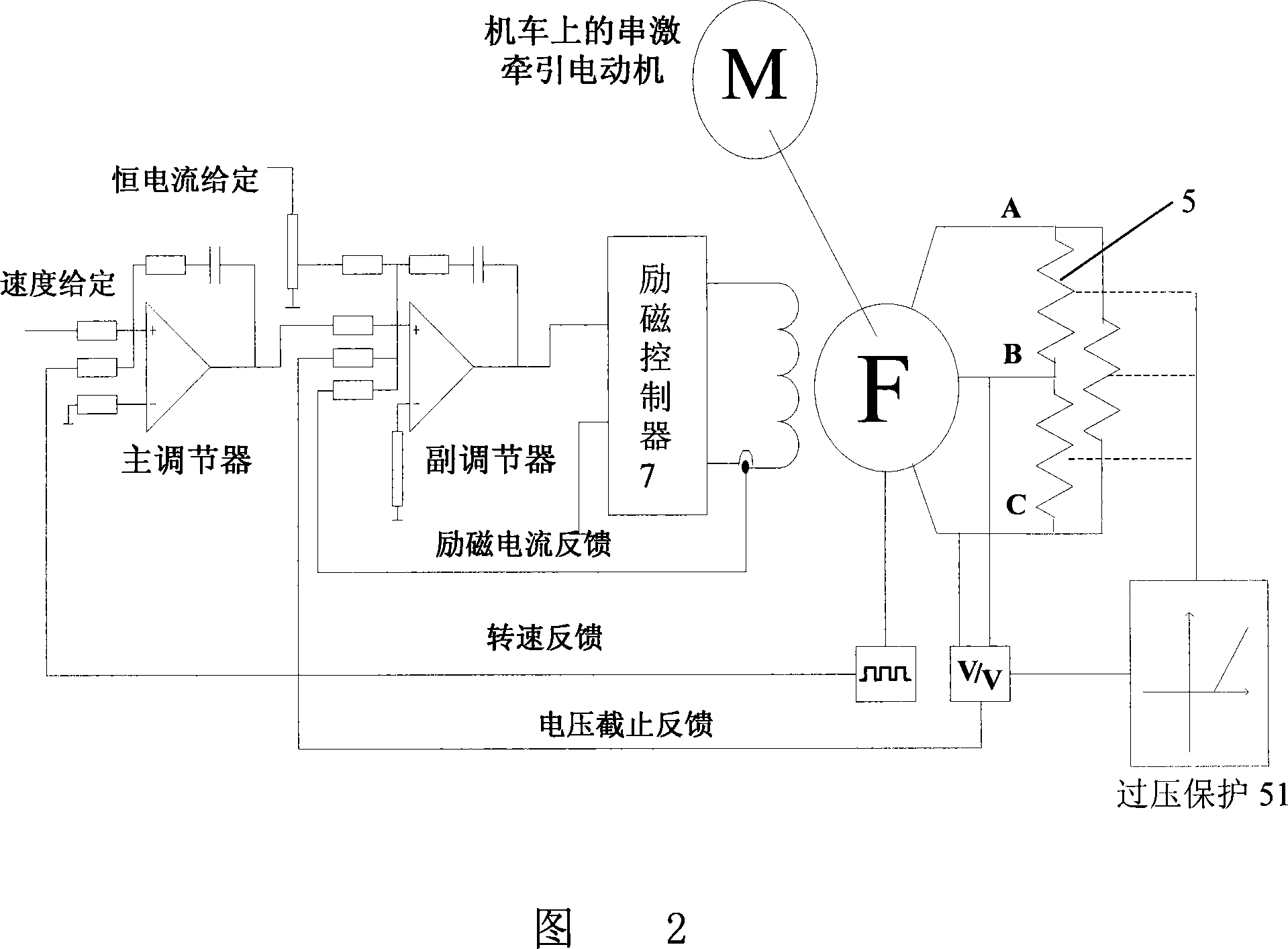
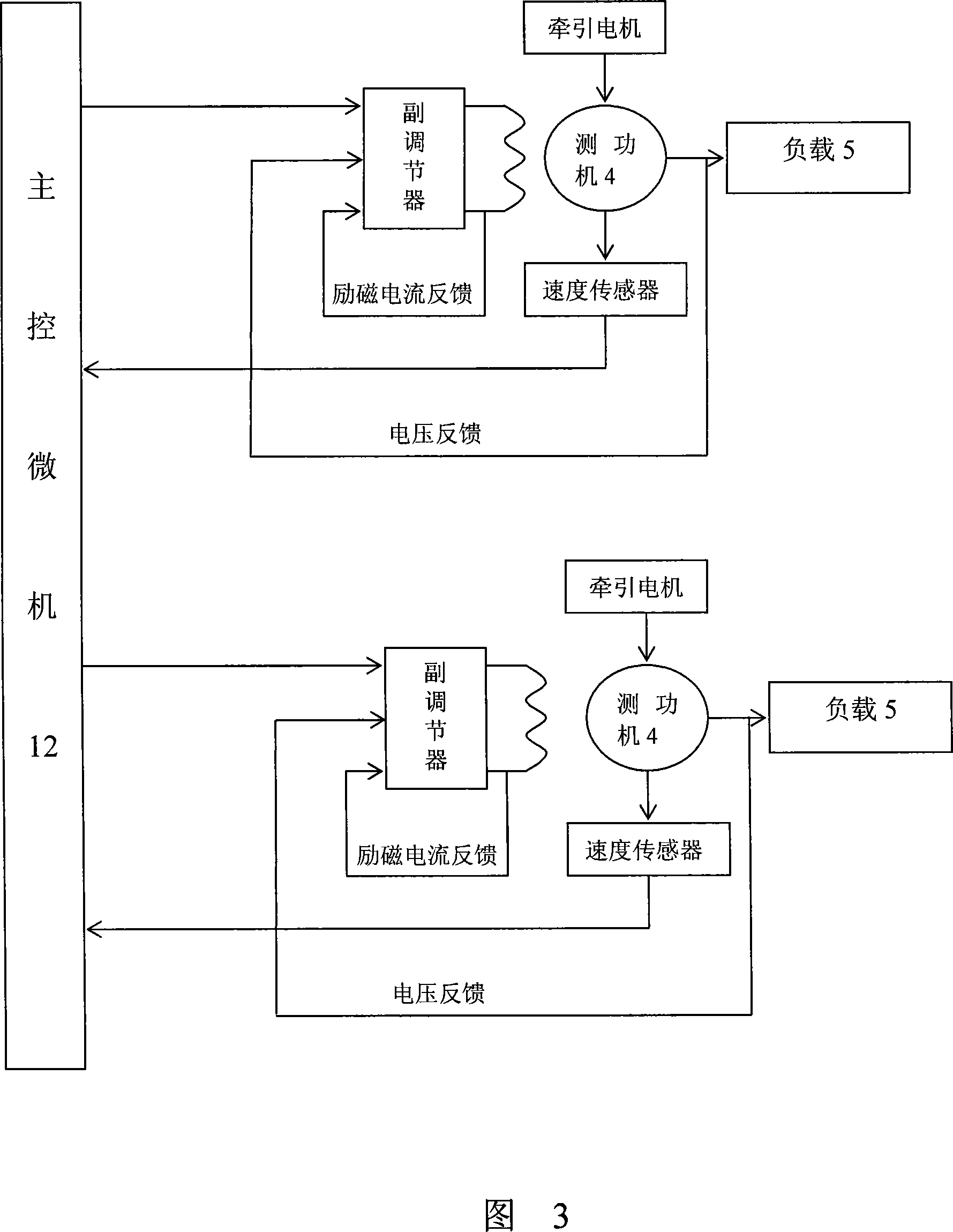
The invention relates to a synchronization control device for wheel pair speed of a locomotive fixation test bed, and is characterized in that the invention comprises six pairs of axles arranged oppositely, and a synchronization control system. Each three pairs are connected into a mechanical synchronizing system. Each of the mechanical synchronizing systems is connected with a transmission system. The two transmission systems are connected with a dynamometer, respectively. The two dynamometers are connected with a load, respectively. The synchronization control system comprises a master governor, a secondary controller, two excitation controllers and two exciter circuits, which are connected in turn. The exciter circuits are connected with the two dynamometers, respectively. The invention can regulate the velocity control and synchronization control of the wheel pairs automatically in the locomotive fixation test, and has the characteristics of excellent following feature and small errors.

Description

technical field [0001] The invention relates to a locomotive test device, in particular to a wheel set speed synchronous control device for controlling the speed of each wheel set of a locomotive in a traction test device. Background technique [0002] At present, my country's railways continue to speed up on a large scale. The increase in train speed has put forward higher requirements for the safety and reliability of locomotive operation. Therefore, it is very necessary to build a locomotive fixed test bench suitable for different structural characteristics and capable of starting test, traction test, braking test, etc. The speed control and speed synchronous control of each wheel set of the locomotive in the fixed test stand of the locomotive are the guarantee for the smooth progress of various traction tests of the locomotive on the fixed test stand. [0003] At present, there is no device to automatically control the synchronous rotation of each wheel pair in the loco...

Claims


Application Information

Patent Timeline
IPC IPC(8): G01M17/08G05B11/32G05B11/42G05B19/05G05B19/418
CPCY02P90/02
Inventor 韩为民朱善君钱利民
Owner CRRC BEIJING ERQI LOCOMOTIVE CO LTD
Learn More