Debug information collection method and debug information collection system

A technology for debugging information and collection methods, applied in the fields of instruments, electrical digital data processing, hardware monitoring, etc., can solve the problem that the indirect time of storage resources is large, the time reduction of storage resources and probe execution time information collection cannot be realized at the same time, and the obstacle is rapid. Efficiently develop software and other issues to achieve the effect of reducing the burden

Inactive Publication Date: 2008-06-18
HITACHI LTD
View PDF1 Cites 3 Cited by
  • Summary
  • Abstract
  • Description
  • Claims
  • Application Information

AI Technical Summary

Problems solved by technology

However, since all the probes are pre-inserted into the program, there is a problem that the overhead time given to memory resources is large.
[0008] That is to say, there is a problem in the technologies described in these documents that the reduction of memory resources and probe execution time when collecting debugging information from many and various devices cannot be realized simultaneously with the reduction of developer-based information collection.
In addition, even if the techniques of the above two documents are combined, deviations in the debugging information collected by the probe cannot be avoided, thus leaving a problem that hinders rapid and efficient software development

Method used


Image

  • Debug information collection method and debug information collection system
  • Debug information collection method and debug information collection system
  • Debug information collection method and debug information collection system

Examples


Embodiment Construction

[0024] Next, embodiments of the present invention will be described with reference to the drawings.

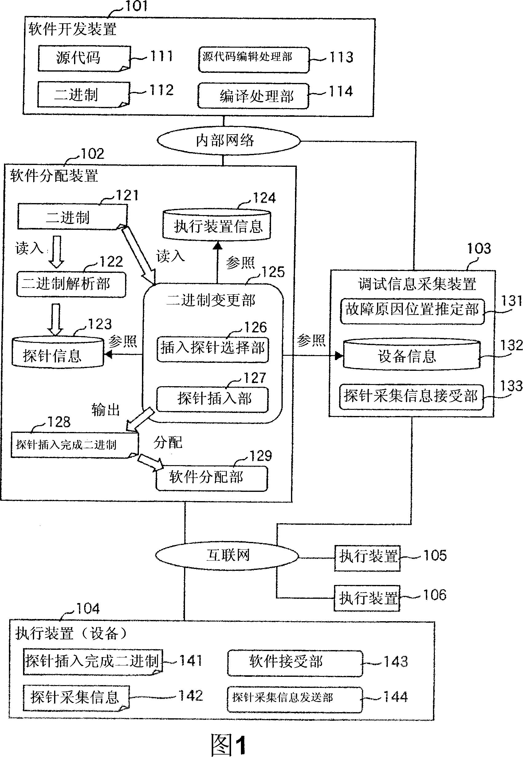
[0025] FIG. 1 is an overall structural diagram of the software distribution system involved in the present invention. This system is composed of a software development device 101, a software distribution device 102, a debugging information collection device 103, and multiple execution devices (equipment) 104, 105, 106, etc. First, the relationship between the respective devices will be described.

[0026] A software developer uses the software development apparatus 101 to develop software and generate executable binaries. The generated binary is sent to the software distribution device 102 via an internal network or the like. The software distribution device 102 inserts a probe into the binary, and distributes the binary to the execution devices 104, 105, 106, etc. via the Internet or the like. Each execution device executes the distributed binary and provides services to t...


PUM


Abstract

The present invention relates to a debugging information collection method and a debugging information collection system. In a software distributing device (102), a binary analysis unit (122) obtains a set of all insertion positions where probes can be inserted into software. The binary change unit (125) determines a parent set of probe insertion positions inserted into the software and the number of probes inserted into each device (104), and selects probes corresponding to the number of inserted probes from the parent set. the insertion position and insert it into the software. At that time, refer to the probe information (123), the execution device information (124), and the debugging information (132). The software distributing unit (129) distributes the software into which the probe is inserted to the device (104). Accordingly, both the burden on the device side and the burden on the software developer can be reduced, and debug information can be acquired uniformly without deviation.

Description

technical field [0001] The present invention relates to a debugging information collection method for software distributed and executed by a plurality of devices connected to a network in order to improve software quality. Background technique [0002] In information processing devices called assembly machines, such as information appliances and mobile phones, the scale of software is increasing. The reason is that due to the addition of functions corresponding to the network and the increase in user requirements, it is required to implement many new functions in a short period of time using software. As the scale of such software increases, it is required to ensure the quality of the software. However, it is difficult to ensure time while ensuring quality, and corresponding measures such as software updates are also required after the product is launched. [0003] As a method of ensuring software quality, there is a method of inserting a probe (probe) for investigating an...

Claims


Application Information

Patent Timeline
Patent Type & Authority Applications(China)
IPC IPC(8): G06F11/28
CPCG06F11/362G06F11/28G06F11/30
Inventor 川崎进一郎野尻彻
Owner HITACHI LTD
Why Eureka
Try Eureka