
Antenna structure

An antenna structure and antenna technology, applied in the directions of the antenna, the antenna grounding device, the antenna support/installation device, etc., can solve the problems such as the inability to flexibly adjust the installation position, the limited effect, and the signal interference.

Inactive Publication Date: 2011-06-01
赵艳杰 +3
View PDF1 Cites 0 Cited by
  • Summary
  • Abstract
  • Description
  • Claims
  • Application Information

AI Technical Summary

Problems solved by technology

However, when the antenna and the notebook computer are transmitting signals, there is a problem of signal interference. Only relying on the grounding design of the antenna at the display panel to eliminate the signal interference problem of the antenna during transmission has limited effect and cannot Enhance the signal strength of the transmission
[0005] Another example is an integrated antenna for notebook computers disclosed in US Patent No. US6,339,400, please refer to US Patent No. US6,339,400 figure 1 As shown, it sets one or more antennas around the screen of the notebook computer. However, since the ground terminal of each antenna must be connected to the ground of the screen or its frame, the installation position of the large wire is in the configuration design. Restricted and unable to flexibly adjust the installation position according to design requirements

Method used


Image

  • Antenna structure
  • Antenna structure
  • Antenna structure

Examples


Embodiment Construction

[0030] In order to have a further understanding of the purpose, structure, features, and functions of the present invention, the following detailed descriptions are provided in conjunction with the embodiments.

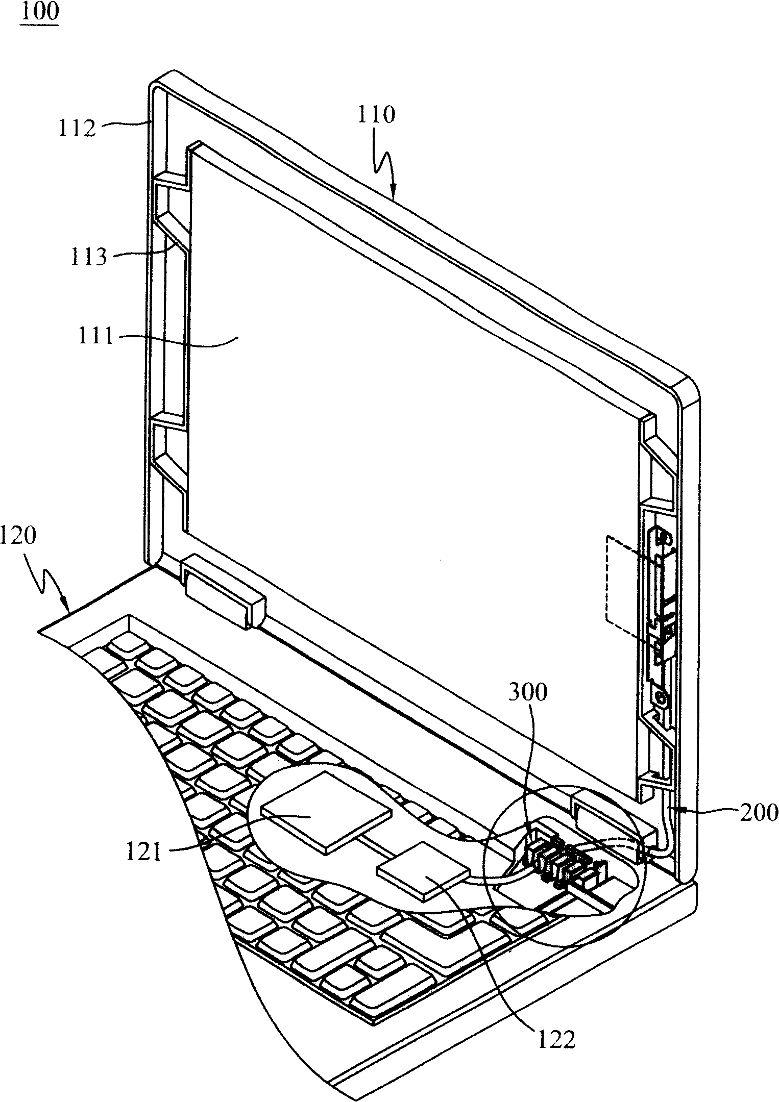
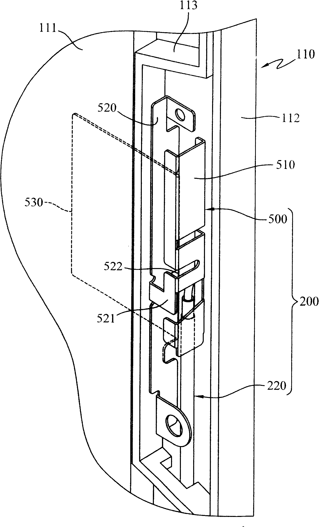
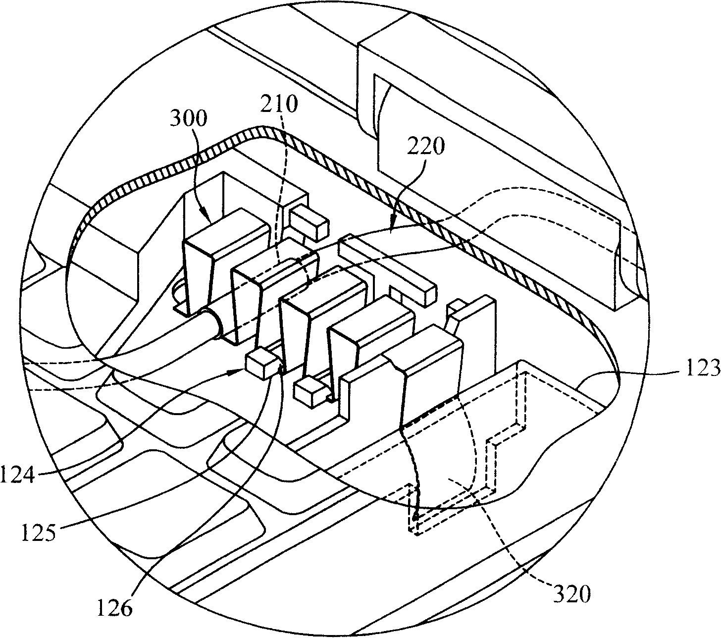
[0031] see figure 1 As shown, the antenna structure disclosed in the present invention includes the antenna 200 and the ground component 300 , and is applied to the notebook computer 100 . The notebook computer 100 includes a display screen 110 and a host 120 pivotally connected to the display screen 110. The display screen 110 and the host 120 serve as output and input interfaces respectively, and the host 120 also includes a processor 121 and a signal connected to the processor 121. conversion module 122 . One end of the antenna 200 is disposed on the display screen 110 , and the other end of the antenna 200 extends to the signal conversion module 122 of the host 120 for transmitting wireless signals to the signal conversion module 122 . The signal conversion modu...


PUM


Abstract

The invention provides an antenna structure which is applied to a notebook computer. The notebook computer comprises a display screen and a host computer. The host computer of the notebook computer is provided with a grounding part; the antenna structure comprises an antenna and a grounding component; one end of the antenna is arranged at the screen of the notebook computer and the other end thereof is extended to the host computer; the antenna is provided with a grounding section. The grounding component is arranged beside the grounding part and comprises a clamping part and a pushing part which extends from the clamping part; the clamping part clamps and is electrically connected with the grounding section; the pushing part is contacted with the grounding part, thus leading the antenna to be electrically conductive with the grounding part to form a grounding loop, thereby improving the grounding effect and being convenient for assembly.

Description

technical field [0001] The present invention relates to an antenna structure, in particular to an antenna structure in which the antenna is pulled to the grounding part of the main machine and then grounded. Background technique [0002] Wireless Wide Area Network (WWAN) and Wireless Local Area Network (WLAN) refer to a local area network that uses high-frequency wireless electromagnetic waves to communicate between different nodes, which is different from the traditional use of cables. The method of online transmission can be transmitted without physical material, so it can avoid the troubles of wiring and environmental obstacles, and provide the function of roaming for users, so as to reach the network environment anytime and anywhere. [0003] In the transmission technology of the wireless local area network, there are different methods such as microwave, spread spectrum, and infrared rays. In order to enable the notebook computer to roam in the wireless local area netwo...

Claims


Application Information

Patent Timeline
Patent Type & Authority Patents(China)
IPC IPC(8): H01Q1/22H01Q1/48H01Q13/00
Inventor 何佳儒
Owner 赵艳杰
Learn More