Non-bur CMOS radio frequency divider based on phase switch

A burr-free frequency divider technology, which is applied to the automatic control of power, synchronous pulse counters, electrical components, etc., can solve problems such as complex, large burrs in CMOS RF frequency dividers, and limit the maximum speed, so as to improve the working speed, Avoid the use of logic gates and eliminate the effect of glitch signals

Active Publication Date: 2008-06-18
SHANGHAI HUAHONG GRACE SEMICON MFG CORP
View PDF0 Cites 1 Cited by
  • Summary
  • Abstract
  • Description
  • Claims
  • Application Information

AI Technical Summary

Problems solved by technology

It is more complicated to realize dual-mode operation, and 2-level logic gates need to be inserted in the signal loop, and the delay caused by inserting logic gates limits the highest speed that can be achieved
Moreover, the CMOS RF frequency divider realized by this method has a large burr

Method used


Image

  • Non-bur CMOS radio frequency divider based on phase switch
  • Non-bur CMOS radio frequency divider based on phase switch
  • Non-bur CMOS radio frequency divider based on phase switch

Examples


Embodiment Construction

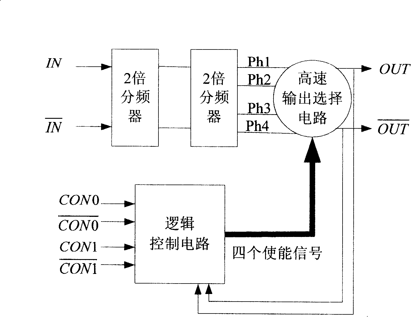
[0016] like figure 1 Shown is the structural block diagram of the burr-free CMOS RF frequency divider of the present invention, which mainly includes a four-phase prescaler, a high-speed output selection circuit and a logic control circuit.

[0017] Among them, the four-phase prescaler is based on two input signals IN and IN with opposite phases to provide four reference signals Ph1, Ph2, Ph3 and Ph4 whose phases are sequentially different by 90 degrees to the high-speed output selection circuit. The phase timing diagram can be like figure 2 As shown; the period of these reference signals is four times the period of the input signal, so the phase difference of 90 degrees is exactly one period of the input signal. In one embodiment, the four-phase prescaler can be implemented by cascading two CML two-frequency dividers.

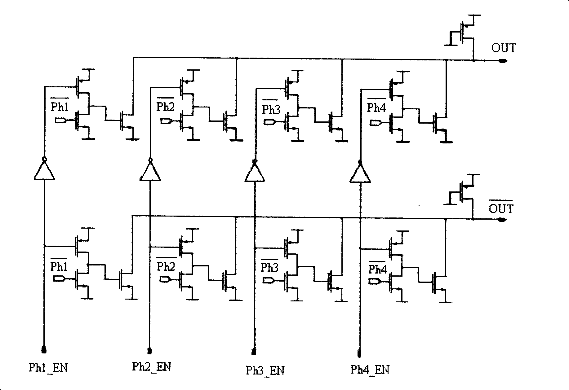
[0018] The high-speed output selection circuit is used to switch the output signals OUT and OUT in the order of Ph1->Ph2->Ph3->Ph4->Ph1 according to the en...


PUM


Abstract

The invention discloses a no-burr CMOS RF frequency divider which is based on multi-phase shifting. The invention can implement dual mode output of 4/5 division frequency ratio, radically eliminates the possibility of burr signal generation when the phase is shifted, and improves the working speed of the RF frequency divider. The no-burr CMOS RF frequency divider comprises a four-phase prescaler which is used for providing four benchmark signals with difference of 90 DEG sequentially to a high-speed output selection circuit; the output terminal of the high-speed output selection circuit comprises a 'logic or' operation; a logic control circuit is used for outputting enabling signals which can be shifted according to the output signals of the high-speed output selection circuit.

Description

technical field [0001] The invention relates to a CMOS radio frequency divider, in particular to a burr-free CMOS radio frequency divider based on phase switching. Background technique [0002] RF frequency dividers are an important part of phase-locked logic (PLL) circuits. The RF signal generated by a voltage-controlled oscillator (VCO) generally passes through a specially designed RF frequency divider before it can be processed by a subsequent simple CMOS frequency divider. In discrete device designs, RF dividers are typically implemented using bipolar semiconductors. [0003] Due to cost advantages and the ability to realize large-scale digital circuits cheaply, CMOS technology has been widely used. However, even in deep submicron CMOS technology, the general CMOS frequency divider based on basic flip-flops can only handle hundreds of M Hz signal, so it is of great significance to propose a high-performance CMOS RF frequency divider based on current mode operation. ...

Claims


Application Information

Patent Timeline
Patent Type & Authority Applications(China)
IPC IPC(8): H03K23/52H03K21/10H03L7/085H03L7/193
Inventor 雷宇朱红卫唐成伟陈美娜
Owner SHANGHAI HUAHONG GRACE SEMICON MFG CORP
Why Eureka
Try Eureka