Fixed parts for circuit board

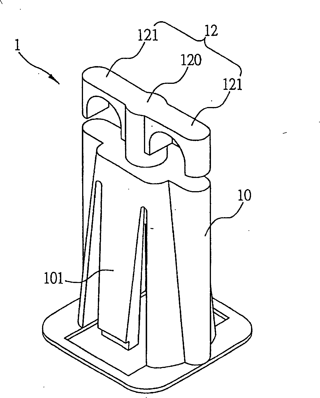
A technology for fixing components and circuit boards, which is applied to digital data processing components, circuit layout on support structures, casing/cabinet/drawer components, etc., which can solve the problem of taking up space on the motherboard, large space, and inability to rotate the shaft 120 fixed other issues

Active Publication Date: 2008-06-18
SHANGHAI MUNICIPAL ELECTRIC POWER CO
View PDF0 Cites 2 Cited by
  • Summary
  • Abstract
  • Description
  • Claims
  • Application Information

AI Technical Summary

Problems solved by technology

[0006] Although the fixing part 1 can preliminarily realize the purpose of fixing the motherboard, it has two wings 121, so the hole provided on the motherboard must be at least slightly larger than the area of ​​the two wings 121, thus occupying the space on the motherboard. Further, the wiring on the motherboard is limited, and when multiple fixed parts 1 are used on the motherboard, the occupied space is larger
[0007] Moreover, the two wings 121 of the rotating shaft 120 of the fixed component 1 can have the best effect of pressing the main board after turning 90 degrees. Nowadays, the technical field also limits the rotation of the rotating shaft to 90 degrees, but the rotating shaft 120 cannot be fixed. Because of the specific rotation angle, the two wings 121 are easy to loosen due to vibration or other external forces
[0008] Furthermore, the hollow housing 10 of the fixing part 1 is only used to support the main board and cannot limit the lateral movement of the main board, so that the main board is easy to slide when it is transported or subjected to external force

Method used


Image

  • Fixed parts for circuit board
  • Fixed parts for circuit board
  • Fixed parts for circuit board

Examples


Embodiment Construction

[0050] The implementation of the present invention will be described below through specific specific examples. Please describe the specific examples of the present invention with reference to the figures below, so that those skilled in the art can easily understand the technical features and achieved effects of the present invention.

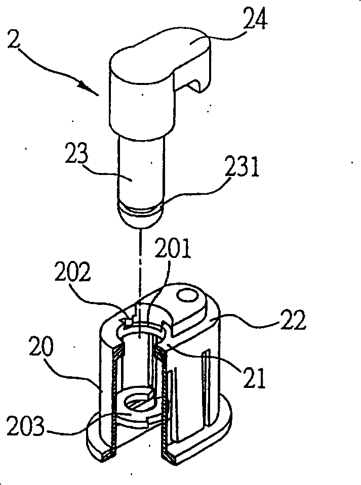
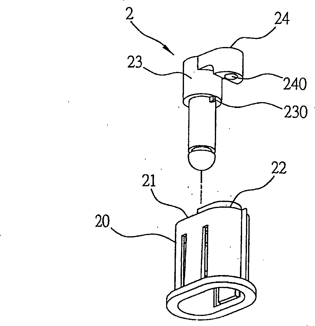
[0051] see figure 2 and image 3 , the fixing part 2 for the circuit board of the present invention has a hollow shell 20, and the hollow shell 20 can define a first end 21 and a second end 22 in the horizontal direction, and at the first end 21 A rotating shaft 23 is rotatably combined in the middle, and the top of the rotating shaft 23 is exposed on the top of the hollow housing 20, and a pressing arm 24 extending from the top of the rotating shaft 23 to the second end 22 is provided. By supporting a circuit board on the top of the hollow housing 20, and fixing the bottom of the hollow housing 20 on the chassis floor of an electronic device,...


PUM


Abstract

A fixed part for a circuit board is used for fixing the circuit board on the bottom plate of the crate of the electronic device, and the fixed part comprises a hollow shell, the top and the bottom of the hollow shell are respectively fixed on the bottom plate of the crate to support the circuit board. The hollow shell comprises a first end part and a second end part in the horizontal direction and the first end part is rotationally combined with a shaft, the top of the shaft exposes from the top of the hollow shell, and the top of the shaft is provided with a pressing arm, the terminal end of the pressing arm extends to the second part. By rotating the shaft, the terminal end of the pressing end presses the circuit board, thereby fixing the circuit board on the bottom plate of the crate.

Description

technical field [0001] The invention relates to a fixing part, in particular to a fixing part for a circuit board. Background technique [0002] The mainboard is fixed on the bottom plate of the chassis such as a server or personal computer by using screws to support the mainboard and fixing it to the bottom plate of the chassis. In recent years, in order to improve the convenience of installing the mainboard, a plastic and tool-free Fixed fixtures came into being. [0003] see figure 1 , the fixed part 1 includes a hollow shell 10, a flange 11 arranged at the bottom of the hollow shell 10, and a pressing part 12 rotatably coupled to the top of the hollow shell 10, wherein the hollow shell 10 has The lateral shrapnel 101 and the pressing part 12 are composed of a rotating shaft 120 and two wing parts 121 extending from both sides of the rotating shaft 120 , and there is a gap between the two wing parts 121 and the hollow casing 10 . [0004] The chassis bottom plate (not ...

Claims


Application Information

Patent Timeline
IPC IPC(8): H05K7/02H05K5/02G06F1/16
Inventor 张林伟
Owner SHANGHAI MUNICIPAL ELECTRIC POWER CO
Why Eureka
Try Eureka