Installation for producing sterile bottles by blow molding sterilized preforms

A technology of preforms and equipment, applied in the direction of disinfection, bottle filling, liquid bottling, etc., which can solve problems such as uneven deposition

Active Publication Date: 2008-06-18
SIDEL PARTICIPATIONS SAS
View PDF2 Cites 23 Cited by
  • Summary
  • Abstract
  • Description
  • Claims
  • Application Information

AI Technical Summary

Problems solved by technology

[0021] [21] However, turbulence causes residual droplets of dis

Method used


Image

  • Installation for producing sterile bottles by blow molding sterilized preforms
  • Installation for producing sterile bottles by blow molding sterilized preforms
  • Installation for producing sterile bottles by blow molding sterilized preforms

Examples


Embodiment Construction

[0046] [46] In the following, similar or identical components are designated with the same reference numerals.

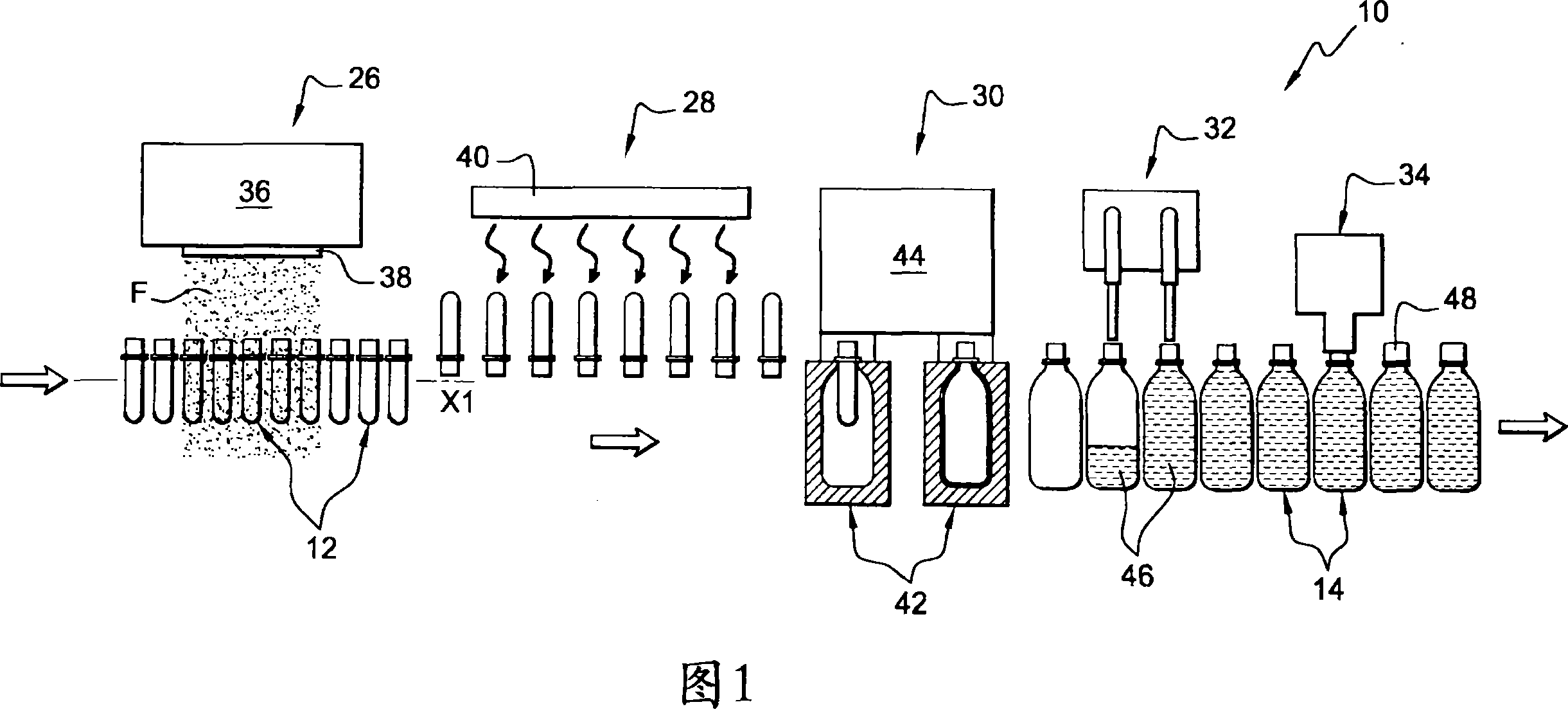
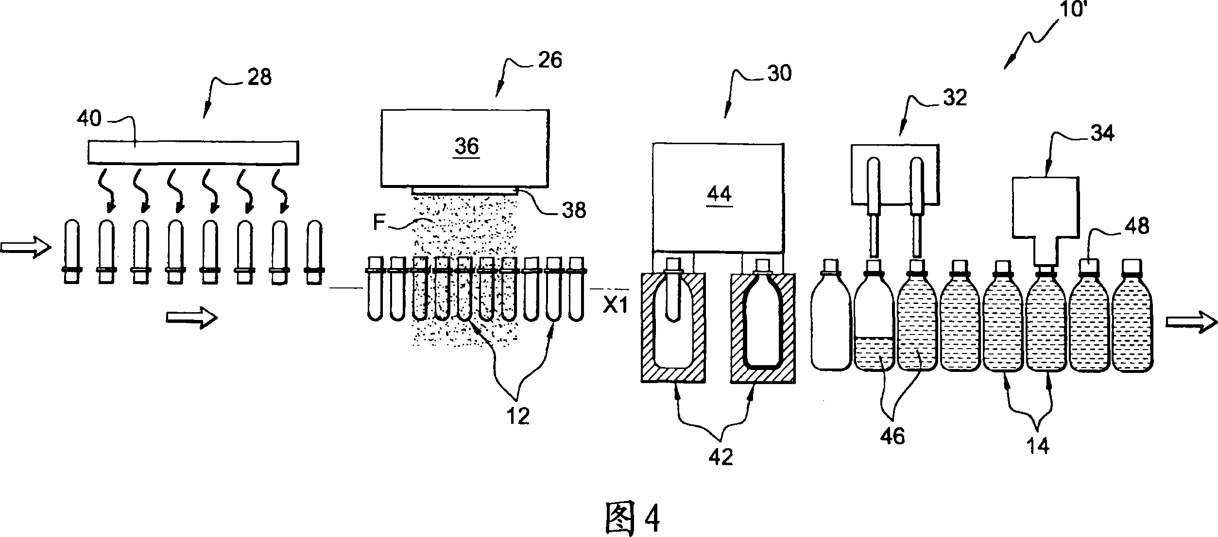
[0047] [47] FIG. 1 shows an apparatus 10 for producing bottles 14 from plastic preforms 12 by blowing.

[0048] [48] ​​Such a device 10 is used, for example, for manufacturing plastic bottles 14, the plastic material being, for example, polyethylene terephthalate (PET).

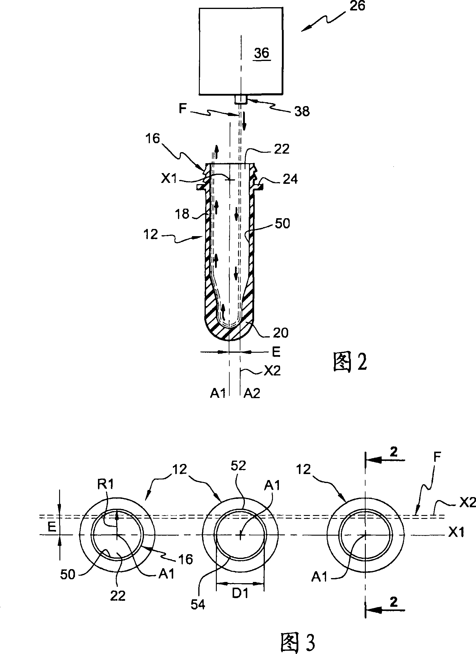
[0049] [49] Each preform 12 generally has the shape of a tube, one end of which is closed, and the other end already has the final shape of the neck 16 of the bottle 14.

[0050] [50] As a non-limiting example, FIG. 2 shows the preform 12 with the axis A1 of its cylindrical body 18 extending vertically.

[0051] [51] The axis A1 of the main body 18 coincides with the axis of the neck 16.

[0052] [52] The lower end 20 of the preform 12 is closed, while its upper end forms a neck 16 which defines an opening 22 and is provided with an outer radial flange 24 here.

[0053] [53] Here, the preform 12 is mad...


PUM


Abstract

The invention proposes a plant for the production of sterile bottles by blowing from preforms (12), which has a disinfection unit (26), a heat conditioning unit, a molding unit, the disinfection unit (26) has a spraying device (36), The spraying device is equipped with nozzles (38) which, over each preform (12), direct a stream of vaporized sterilizing agent (F ) into the preform (12), said central injection axis (A2) being generally parallel to the axis (A1) of the preform (12) during processing and offset radially from the preform (12) axis (A1).

Description

Technical field [0001] [01] The present invention relates to equipment for producing sterile bottles by blowing plastic preforms. [0002] [02] The present invention particularly relates to such an equipment for producing sterile bottles by blowing plastic preforms, wherein the preforms are conveyed into the equipment in a continuous flow from upstream to downstream, and the equipment has : [0003] [03]-A disinfection treatment unit, which has a spray device equipped with at least one nozzle, which sprays a jet-like disinfectant stream toward the neck of each preform during the treatment process to Disinfect at least the inner wall of the preform, [0004] [04]-a thermal conditioning unit with at least one furnace for heating the preform, [0005] [05]-a molding unit having at least one mold and at least one blowing device, the blowing device subjecting each preform to internal overpressure so that the preform assumes the shape of the mold cavity, Thus forming a bottle. Backgrou...

Claims


Application Information

Patent Timeline
IPC IPC(8): B65B55/10B65B3/02
CPCB65B55/10B29C49/42A61L2/04A61L2202/23A61L2/208B67C2003/227B65B3/022B29C49/42418
Inventor E·阿德里安森斯S·埃贝尔
Owner SIDEL PARTICIPATIONS SAS
Why Eureka
Try Eureka