
Door shoe with anti-noise and non-vibration skill
An anti-noise, guide shoe technology, applied in door/window fittings, transportation and packaging, wing leaf suspension, etc., can solve problems such as increased management costs, unpleasant passengers or users, and reduced elevator reliability.
- Summary
- Abstract
- Description
- Claims
- Application Information
AI Technical Summary
Problems solved by technology
Method used
Image

Examples
Embodiment Construction
[0017] In the following, reference will be made to the attached Figure 3-6 Embodiments of the present invention will be described in detail. However, the following description and drawings are for illustrating the present invention and should not be construed as limiting the present invention.
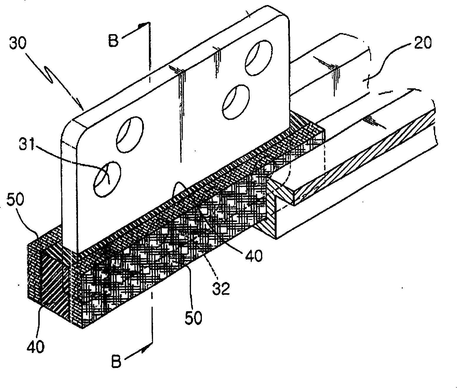
[0018] image 3 A perspective view for explaining the structure and state of using the door guide shoe according to the present invention.
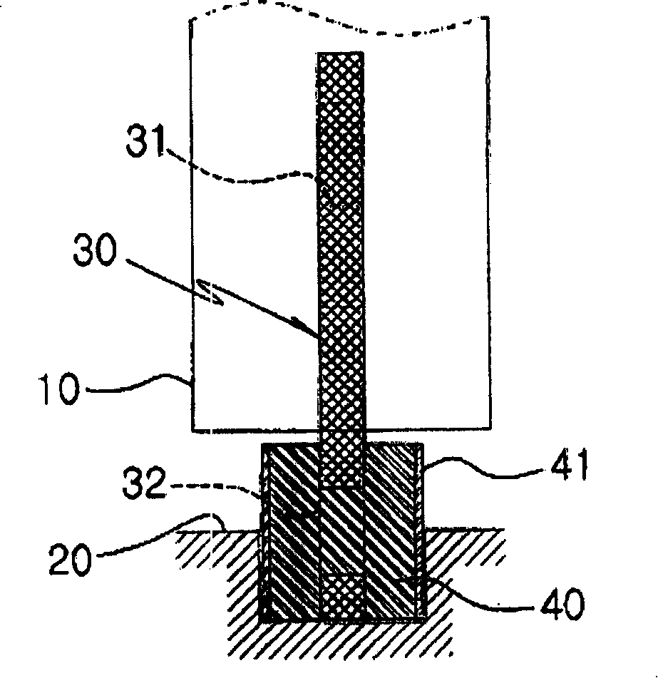
[0019] refer to image 3 , the door guide shoe mainly includes a clamping part 30 on a plate and a friction part 40 at a lower portion of the clamping part 30 .
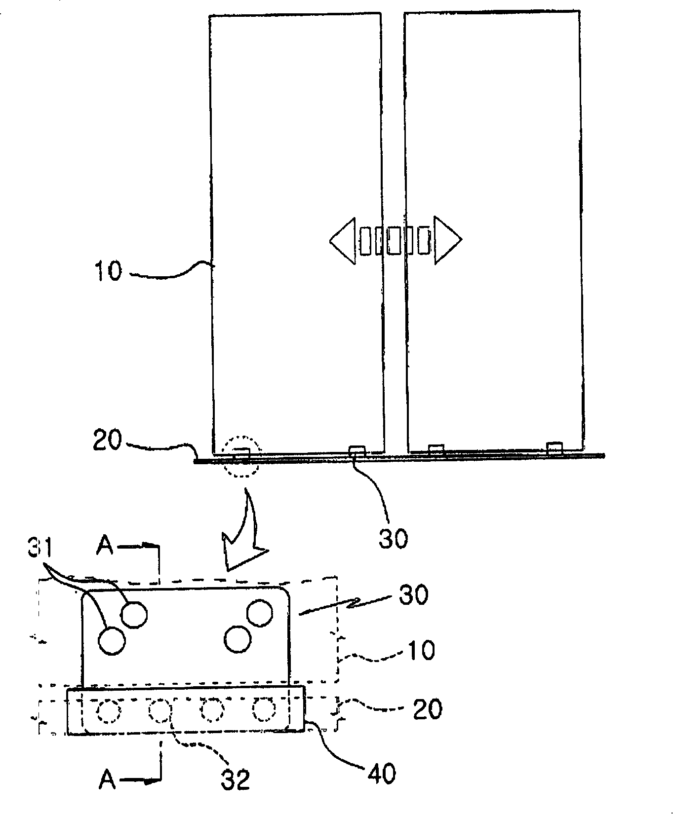
[0020] A door fixing hole 31 is formed in the upper part of the clamping part 30 so as to be fixed on the door (see figure 1 ) so that it can be passed through with bolts, etc. suitable for fixing thereto. A friction member fixing hole 32 is processed on the lower part of the clamping member 30 for fixing the friction member 40, therefore, when the friction member 40 is formed, the...
PUM
 Abstract
Description
Claims
Application Information