Thrust plate and cyclone compressor with the same

A scroll compressor and thrust plate technology, applied in the field of scroll compressors, can solve the problems of increasing wear and hindering the smooth rotation of the rotating shaft 147, so as to achieve the effect of smooth rotation and preventing wear

Inactive Publication Date: 2008-06-25
LG ELECTRONICS (TIANJIN) APPLIANCES CO LTD
View PDF0 Cites 8 Cited by
  • Summary
  • Abstract
  • Description
  • Claims
  • Application Information

AI Technical Summary

Problems solved by technology

That is, when the rotating shaft 147 rotates, debris generated due to wear exists in the thrust surface 149 at the lower end of the rotating shaft 147

Method used


Image

  • Thrust plate and cyclone compressor with the same
  • Thrust plate and cyclone compressor with the same
  • Thrust plate and cyclone compressor with the same

Examples


Embodiment Construction

[0040] Hereinafter, the present invention will be described in detail with reference to the accompanying drawings.

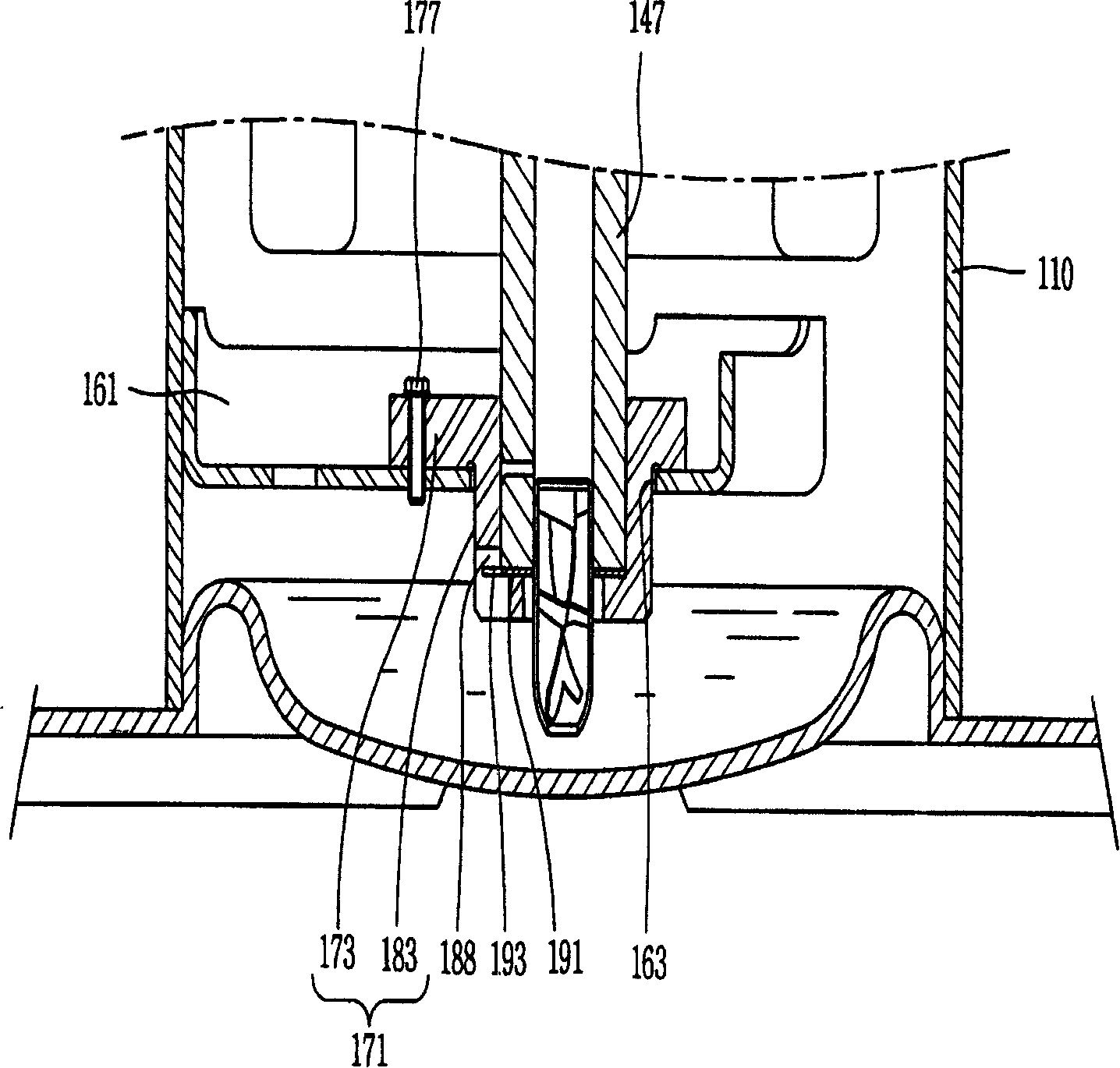
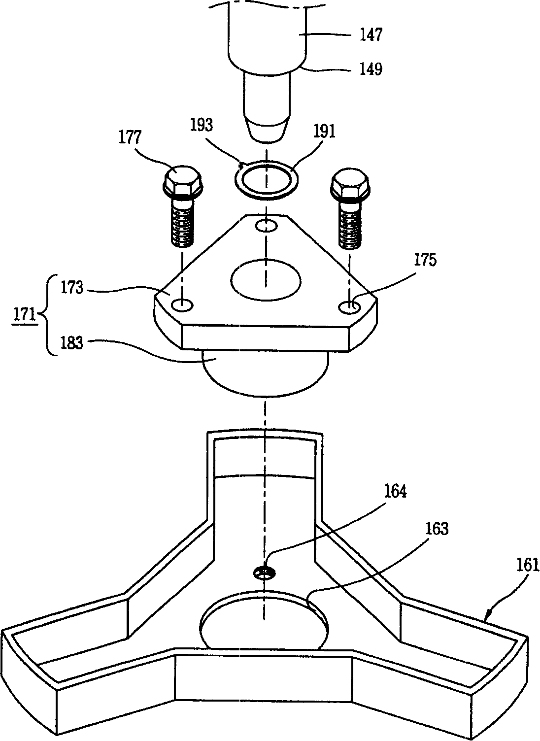
[0041] Figure 5 It is an enlarged cross-sectional schematic diagram of the thrust plate of a scroll compressor with a thrust plate according to an embodiment of the present invention; Figure 6 yes Figure 5 The enlarged cut-away schematic diagram of the thrust plate; Figure 7 yes Figure 5 Plane schematic diagram of the thrust plate; Figure 8 yes Figure 6 Schematic diagram of the debris discharge passage in ; the structure is the same as that of the foregoing and illustrated, and the corresponding parts are omitted from the illustration, and the same symbols are quoted. As shown in the figure, the scroll compressor having the present thrust plate includes a casing 110 which forms a housing space inside; a compression part 121 which is arranged inside the casing 110 and compresses the refrigerant; A rotor 145 rotatably arranged around a rotating shaft ...


PUM


Abstract

The invention relates to a scroll compressor which is relates to a thrust plate and the scroll compressor with the thrust plate. The invention comprises a shell which is provided with an receiving space inside; a compression part which is arranged inside the shell for compressing refrigerant; a motor part which is provided with a stator which is fixedly arranged inside the shell and a stator which can be rotatablely arranged by taking a shaft with a thrust surface at the lower head face as the center; a transverse bearing part for supporting an outer diametral plane of the lower part of the shaft, and a thrust bearing part for supporting the thrust surface of the shaft. The invention is characterized in that the invention also comprises a circular shaped board body, a chip discharge part which is cut on an inner diametral plane of the board body outwards according to the radius direction, and a thrust plate which is placed between the thrust surface and the thrust bearing part. The thrust plate and the scroll compressor with the thrust plate can smoothly discharge the chips generated while the shaft rotating, thereby preventing the abrasion caused by chips.

Description

technical field [0001] The present invention relates to scroll compressors, in particular to thrust plates and scroll compressors with thrust plates. More specifically, the thrust plate and the scroll compressor having the thrust plate of the present invention can smoothly discharge chips generated when the shaft rotates, and can avoid wear caused by chips. Background technique [0002] figure 1 It is a longitudinal sectional view of a conventional scroll compressor. figure 2 yes figure 1 The enlarged schematic diagram of the lower bearing part of . image 3 yes figure 1 The exploded schematic diagram of the lower bearing part. Figure 4 yes figure 2 A schematic diagram of the thrust plate. As shown in the figure, the scroll compressor includes a casing 110 that forms a closed storage space inside, a compression part 121 that compresses the refrigerant, and a motor part 141 that is positioned inside the casing 110 and provides power to the compression part 121. . ...

Claims


Application Information

Patent Timeline
IPC IPC(8): F04C29/00F04C18/02
Inventor 白起大
Owner LG ELECTRONICS (TIANJIN) APPLIANCES CO LTD
Why Eureka
Try Eureka