Torsional vibration damper

A technology of torsional vibration and shock absorber, which is applied in the direction of spring/shock absorber, vibration suppression adjustment, spring, etc. It can solve the problems of small spring capacity and achieve the effect of simplified assembly and simple spring capacity

Inactive Publication Date: 2008-06-25
SCHAEFFLER TECH AG & CO KG
View PDF3 Cites 9 Cited by
  • Summary
  • Abstract
  • Description
  • Claims
  • Application Information

AI Technical Summary

Problems solved by technology

Known torsional vibration dampers have the disadvan

Method used


Image

  • Torsional vibration damper
  • Torsional vibration damper
  • Torsional vibration damper

Examples


Embodiment Construction

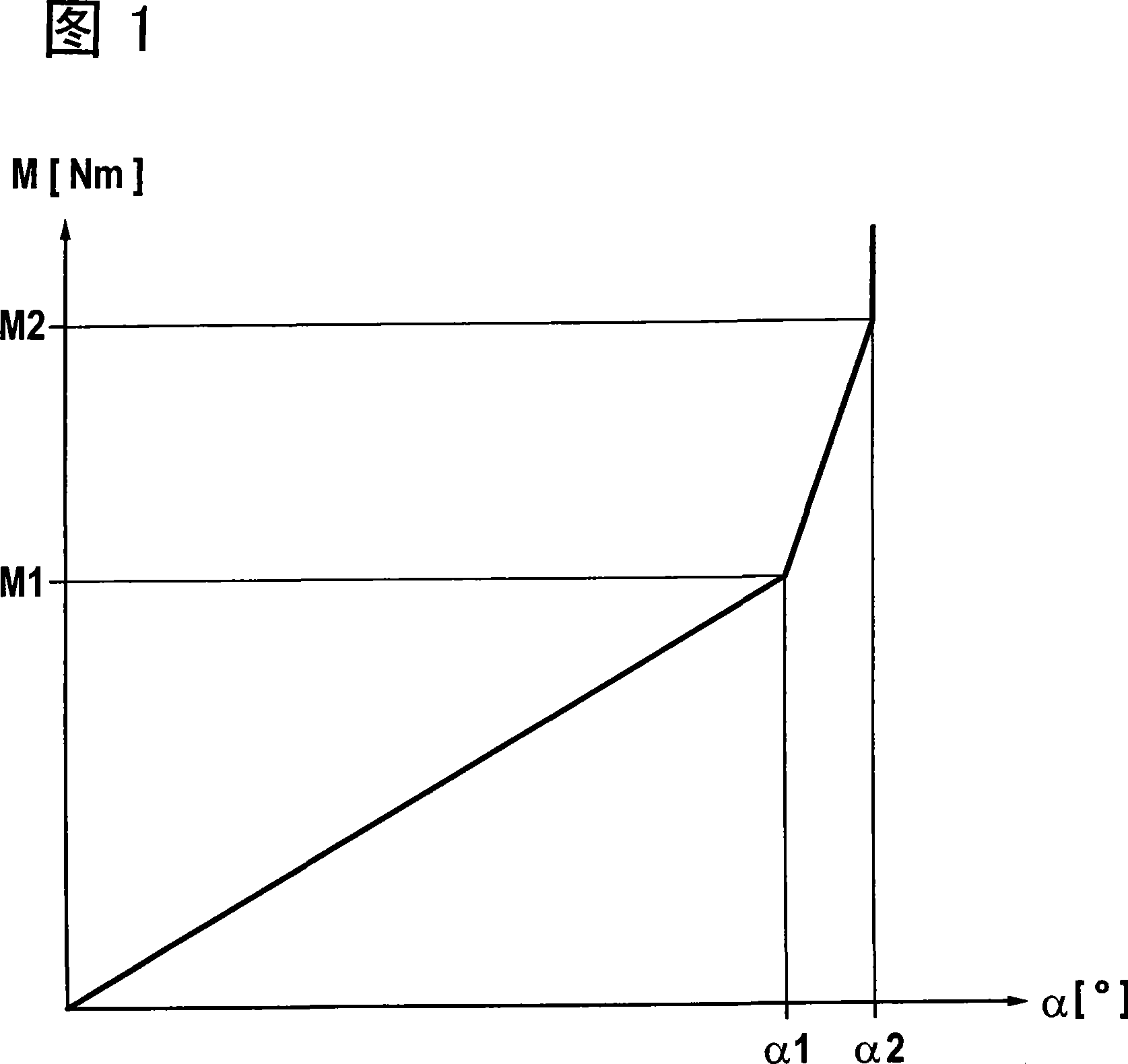
[0029] FIG. 1 shows a Cartesian coordinate diagram in which the torque M in Nm of the torsional vibration damper according to the invention is expressed in degrees in the form of a characteristic curve in the Cartesian coordinate diagram. The relationship between the torsion angle α, this characteristic curve is also called the main shock absorber characteristic curve. The characteristic curve rises linearly from the coordinate origin until a torque M1 corresponding to the maximum engine torque is reached. The dependent torsion angle is α1. In the angular range between α1 and α2 the characteristic curve rises steeply in order to cover the overload moment designated by M2. According to an important aspect of the present invention, a torsional vibration damper is provided, with which the characteristic curve shown in FIG. 1 can be realized in a simple manner. In this case, the known disadvantages of rubber / elastomer springs and of previous steel spring solutions are compensate...


PUM


Abstract

The invention relates to a torsional vibration damper, in particular to a separated flywheel. The invention is provided with an enter piece and an output piece. The output piece stands against the resistance of at least one energy storage device. Besides, the output piece can turn relative to the enter piece from a certain torsional angle, resisting the resistance of a floating stop spring device relative to the energy storage device additively. The invention is characterized in that the stop spring device comprises two end parts coupled with each other, and these end parts can restrictedly move towards the same direction or opposite directions.

Description

technical field [0001] The invention relates to a torsional vibration damper, in particular a split flywheel or clutch disc, with an input part and an output part, which resists the resistance of at least one energy storage device and additionally starting from a defined torsion angle Torsion relative to the input member is resisted by at least one stop spring device that travels relative to the energy storage device. Background technique [0002] Japanese publications JP 2000-205295 A, JP 2000-205296 A and JP 2006-077884 A disclose different embodiments of rubber or elastomer springs which are freely arranged on a steel outer spring device middle. The known torsional vibration dampers have the disadvantage that they have a relatively small spring volume. In addition, it can be compacted vigorously under certain circumstances. Contents of the invention [0003] The object of the present invention is to provide a torsional vibration damper of the type mentioned at the ou...

Claims


Application Information

Patent Timeline
IPC IPC(8): F16F15/123F16F15/134
CPCF16F15/12346F16F15/1234F16F1/128F16F15/12333
Inventor S・莱曼A・皮杜T・哈特曼U・韦勒
Owner SCHAEFFLER TECH AG & CO KG
Why Eureka
Try Eureka