
Crankshaft of reciprocal compressor

A compressor, reciprocating technology, applied in the crankshaft field of reciprocating compressors

Inactive Publication Date: 2008-06-25
SAMSUNG GWANGJU ELECTRONICS CO LTD
View PDF0 Cites 7 Cited by
  • Summary
  • Abstract
  • Description
  • Claims
  • Application Information

AI Technical Summary

Problems solved by technology

[0013] However, in such a reciprocating compressor whose crankshaft rotates in two directions in order to change capacity, since the counterweight is fixed, if the unbalanced rotational force of the crankshaft rotating in two directions is to be compensated more quickly To make the crankshaft perform a balanced rotary motion, there will be many restrictions

Method used


Image

  • Crankshaft of reciprocal compressor
  • Crankshaft of reciprocal compressor
  • Crankshaft of reciprocal compressor

Examples


Embodiment Construction

[0026] Preferred embodiments of the present invention will be described in detail below with reference to the accompanying drawings.

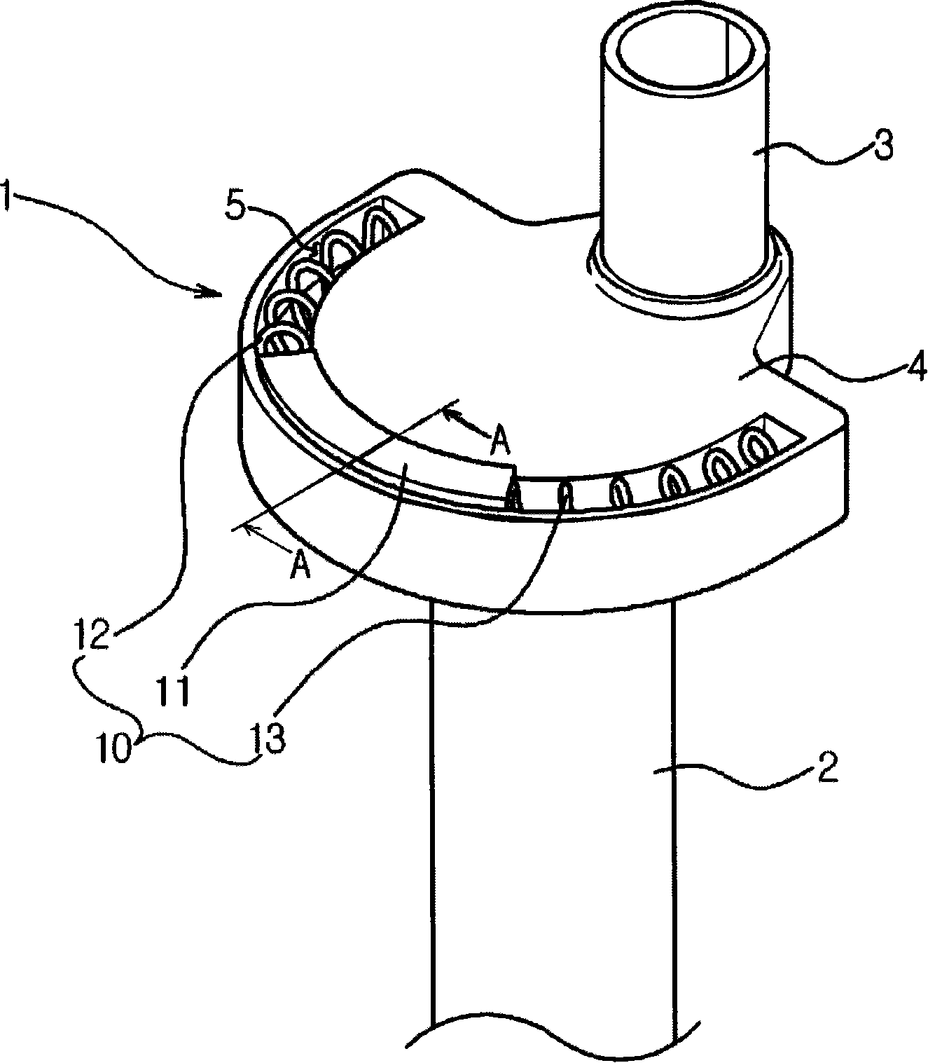
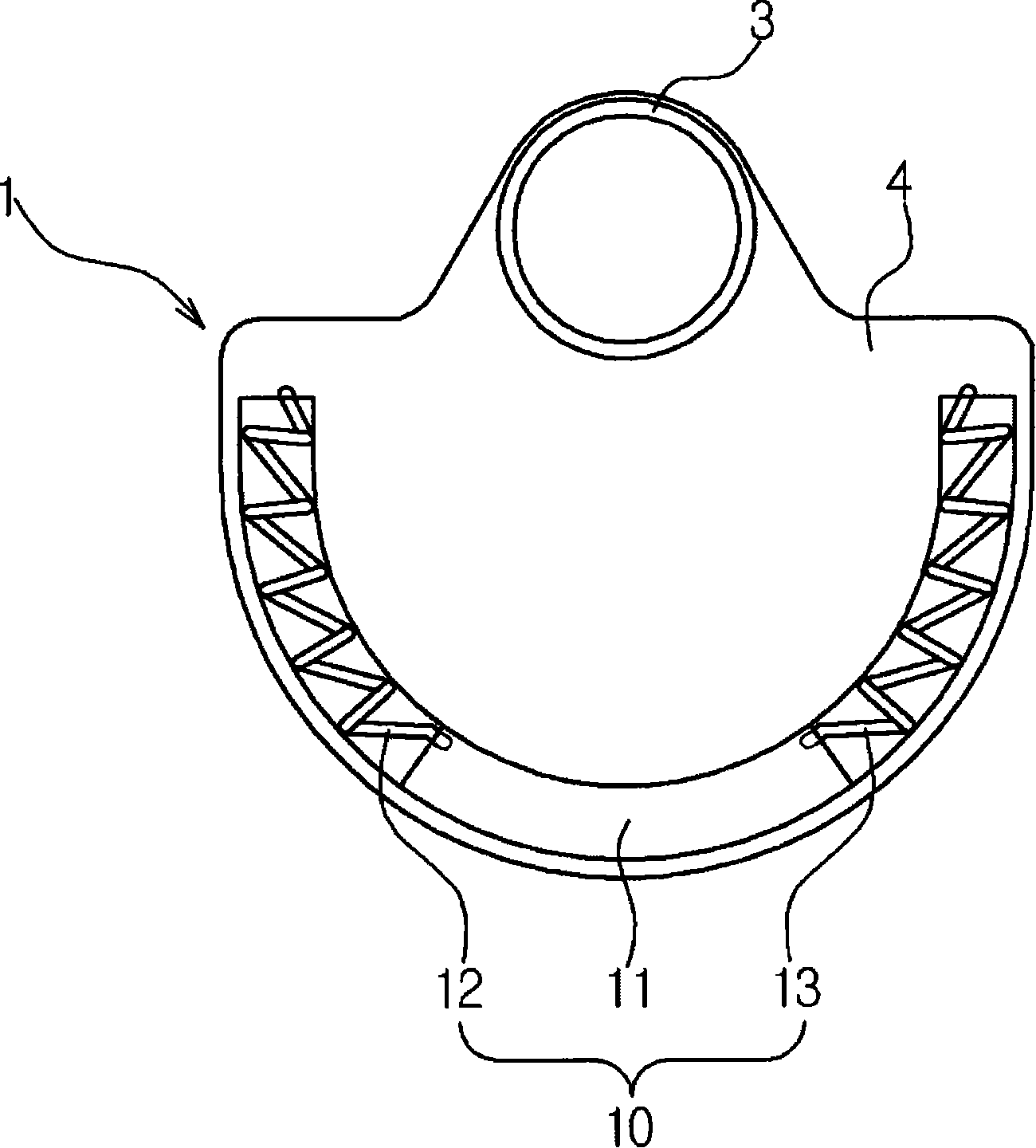
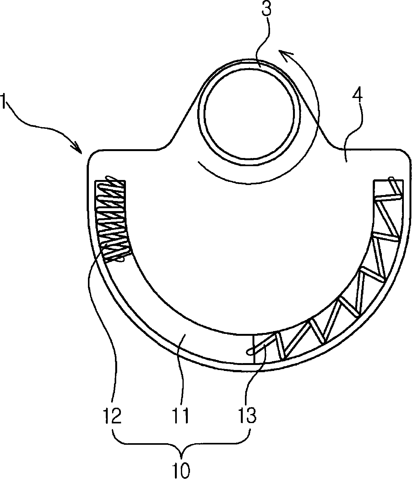
[0027] The crankshaft of the reciprocating compressor provided in this embodiment is applied to the reciprocating compressor, and is used to transmit the driving force of the driving unit providing refrigerant compression power to the piston of the compression unit performing the refrigerant compression function. figure 1 The structure of such a crankshaft 1 provided according to the present embodiment is shown.

[0028] Such as figure 1 As shown, the crankshaft 1 provided by this embodiment has: a main shaft 2, which is pressed into the rotor (not shown) of the drive unit (not shown) and connected to the rotor (not shown) Rotate together; the eccentric shaft 3 that is arranged at one end of the crankshaft 1 and rotates eccentrically, the eccentric shaft 3 is connected with the piston (not shown) through a connecting rod (not shown); between t...


PUM


Abstract

The invention relates to a crank for a reciprocated compressor. The proposal of the invention is to provide a crank for a reciprocated compressor, wherein, the unbalance rotation of the crank can be compensate quickly no matter what the rotation direction when the crank rotates towards two directions. Therefore, the crank for a reciprocated compressor provided by the invention can rotate towards any one of two directions in the drive of a driving unit; one end of the crank is provided with an eccentric shaft which is connected with a piston through a ram; and the lower part of the eccentric shaft is provided with a balance hammer which is used for compensating the unbalance rotation caused by the eccentric shaft. The balance hammer is provided with a weight balancing device which comprises a moving component moved along the rotation direction of the crank and provided with a predetermined quality, and a pair of elastic component for elastically supporting the two ends of the moving component.

Description

technical field [0001] The invention relates to a crankshaft of a reciprocating compressor, in particular to a crankshaft of a reciprocating compressor that can rotate in two directions. Background technique [0002] Generally, a reciprocating compressor is applied in a refrigeration cycle of a refrigerator or an air conditioner to perform a refrigerant compression function, and the reciprocating compressor has its appearance formed by a closed container, and the refrigerant compression is performed by a frame inside such a closed container. Functional compression unit and a drive unit that provides the driving force for refrigerant compression. [0003] First, the drive unit has a stator fixed to the lower outer contour side of the frame and a rotor that rotates according to electromagnetic interaction with the stator. [0004] The driving force of the drive unit is transmitted to the compression unit through the crankshaft. A hollow part is formed in the center of the fra...

Claims


Application Information

Patent Timeline
Patent Type & Authority Applications(China)
IPC IPC(8): F16F15/26F16F15/28F16C3/20F04B39/00
CPCF04B39/0022F04B39/0072F04B39/0094F04B39/121F05B2210/12F05B2210/14F16F3/04Y10S417/00
Inventor 金政贤
Owner SAMSUNG GWANGJU ELECTRONICS CO LTD
Learn More