
Method and device for optimization of flatness control in the rolling of a strip

A flatness and strip technology, applied in metal rolling, measuring devices, profile control, etc., can solve the problems of different flatness control methods in cold rolling mills, and achieve the effect of reducing scrap and improving the output of rolling mills

Active Publication Date: 2008-06-25
ABB (SCHWEIZ) AG
View PDF1 Cites 8 Cited by
  • Summary
  • Abstract
  • Description
  • Claims
  • Application Information

AI Technical Summary

Problems solved by technology

[0023] Traditional flatness control methods for multi-gear cold rolling mills often lead to different problems

Method used


Image

  • Method and device for optimization of flatness control in the rolling of a strip
  • Method and device for optimization of flatness control in the rolling of a strip
  • Method and device for optimization of flatness control in the rolling of a strip

Examples


Embodiment Construction

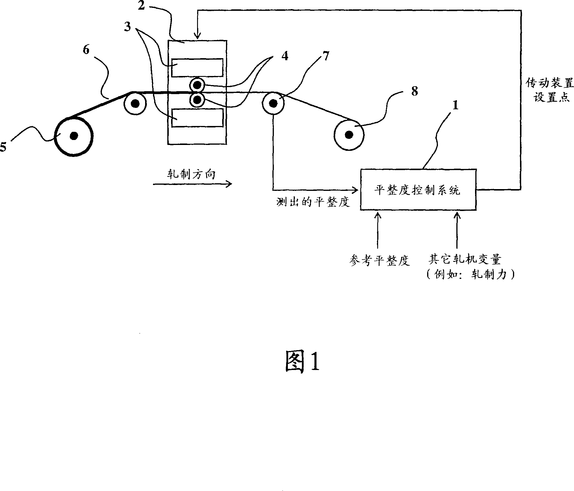
[0040]As shown in FIG. 1 , a flatness control system 1 is integrated in a system comprising a rolling mill stand 2 with several transmissions 3 and rolls 4 . The uncoiler 5 supplies the strip 6 to the rolling stand 2 and passes the strip 6 through the rolling stand 2, whereby the strip 6 passes through a flatness measuring device 7 or a tension detection device, such as a "Stressometer", and Winding machine 8 is rolled up. The mill stand can control the inclination, bending and / or displacement of the rolls 4 . The end product of this rolling process is a rolled strip 6 with the desired flatness.

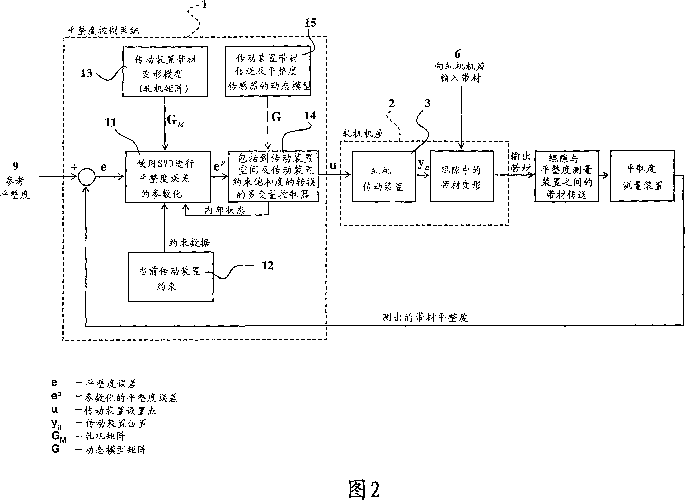
[0041] As can be seen in Figure 2, the flatness control system 1 is designed around a number of front-facing building blocks having all the required functions.

[0042] The reference flatness 9 is compared with the measured strip flatness in a comparator 10 . The resulting flatness error e is supplied to a flatness error parameterization unit 11, and a signal from a first unit 12 ...


PUM


Abstract

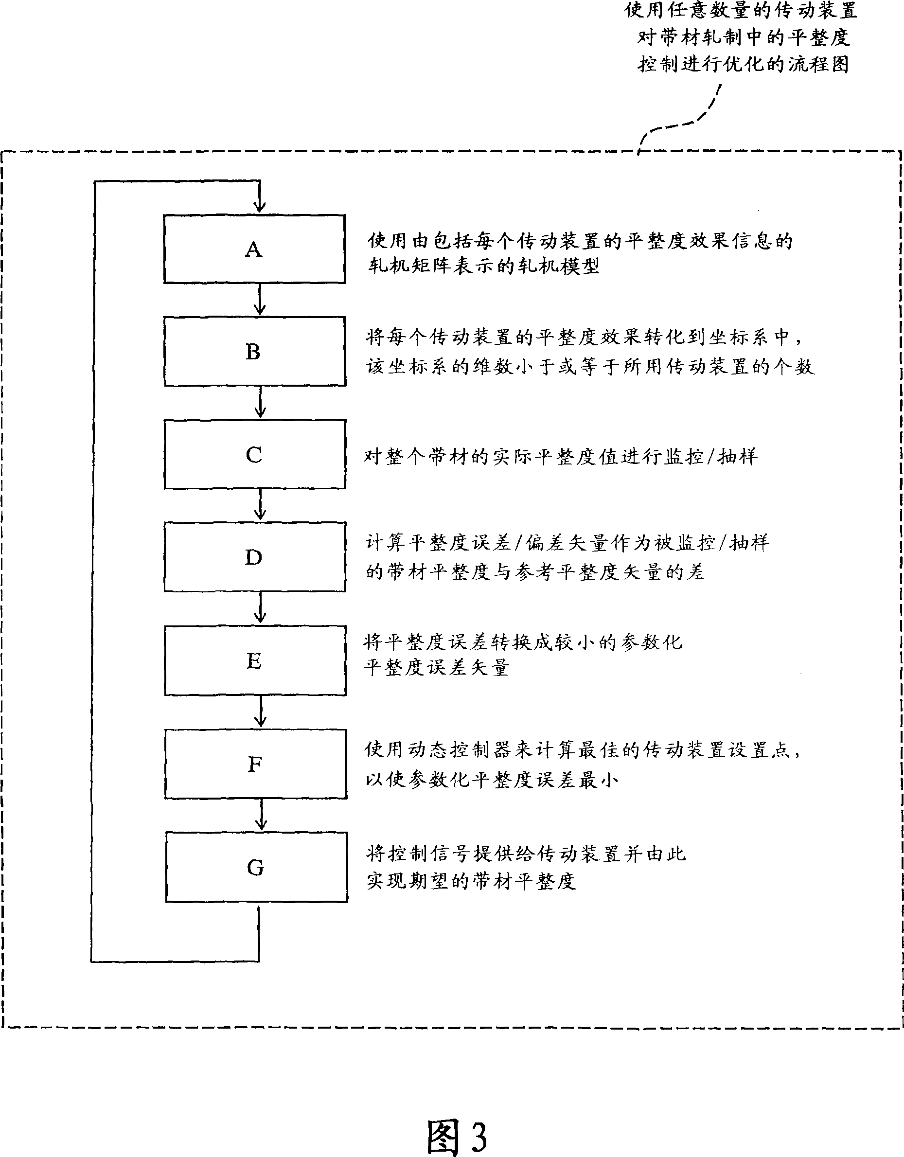
The present invention relates to a method and a device for optimization of flatness control in the rolling of a strip using any number of mill stands and actuators. The invention is achieved by using a mill model represented by a mill matrix that contains information of the flatness effect of each actuator, translating each actuator's flatness effect into a coordinate system, whose dimension is less or equal than the number of actuators used, monitoring / sampling the actual flatness values across the strip, computing a vector of the flatness error / deviation as the difference between the monitored / sampled strip flatness and a reference flatness vector, converting the flatness error into a smaller parameterized flatness error vector, using a dynamic controller to calculate optimized actuator set-points in order to minimize the parameterized flatness error, thereby achieving the desired strip flatness. The invention also relates to a system for optimization of flatness control in the rolling of a strip.

Description

technical field [0001] The present invention relates to a method and apparatus for flatness control of rolled product produced using any number of mechanical or other transmission devices. [0002] The flatness of the rolled product, that is, the strip, is determined by the gap profile of the work rolls of the rolling mill and the thickness profile of the rolled strip. Strip flatness can then be influenced by the manipulation of different control devices that affect the work-nip distribution. Such drives may be mechanical devices such as work roll bending, intermediate roll bending, tilting devices, intermediate roll shifting, crown drives, or thermal devices such as work roll cooling / heating. [0003] The present invention relates to a method and apparatus for determining the set point of a control device (or transmission), wherein the determination of the set point of the control device (or transmission) is achieved by using a method comprising any linear multivariable cont...

Claims


Application Information

Patent Timeline
Patent Type & Authority Applications(China)
IPC IPC(8): B21B37/28G01B11/30
CPCB21B37/42B21B37/38B21B37/40B21B37/28B21B38/02
Inventor 蓬图斯·贝里斯滕
Owner ABB (SCHWEIZ) AG
Learn More