
Mop cleaning cloth fixing structure

A fixed structure, cleaning cloth technology, applied in cleaning equipment, cleaning machinery, carpet cleaning, etc., can solve the problems of insufficient clamping force, pinching of the user's fingers, and the elastic force of the elastic sheet body 4 cannot be fully applied, so as to increase the Safety effect, effect of preventing pinching of the pinch

Inactive Publication Date: 2008-07-02
杨雅箐
View PDF0 Cites 11 Cited by
  • Summary
  • Abstract
  • Description
  • Claims
  • Application Information

AI Technical Summary

Problems solved by technology

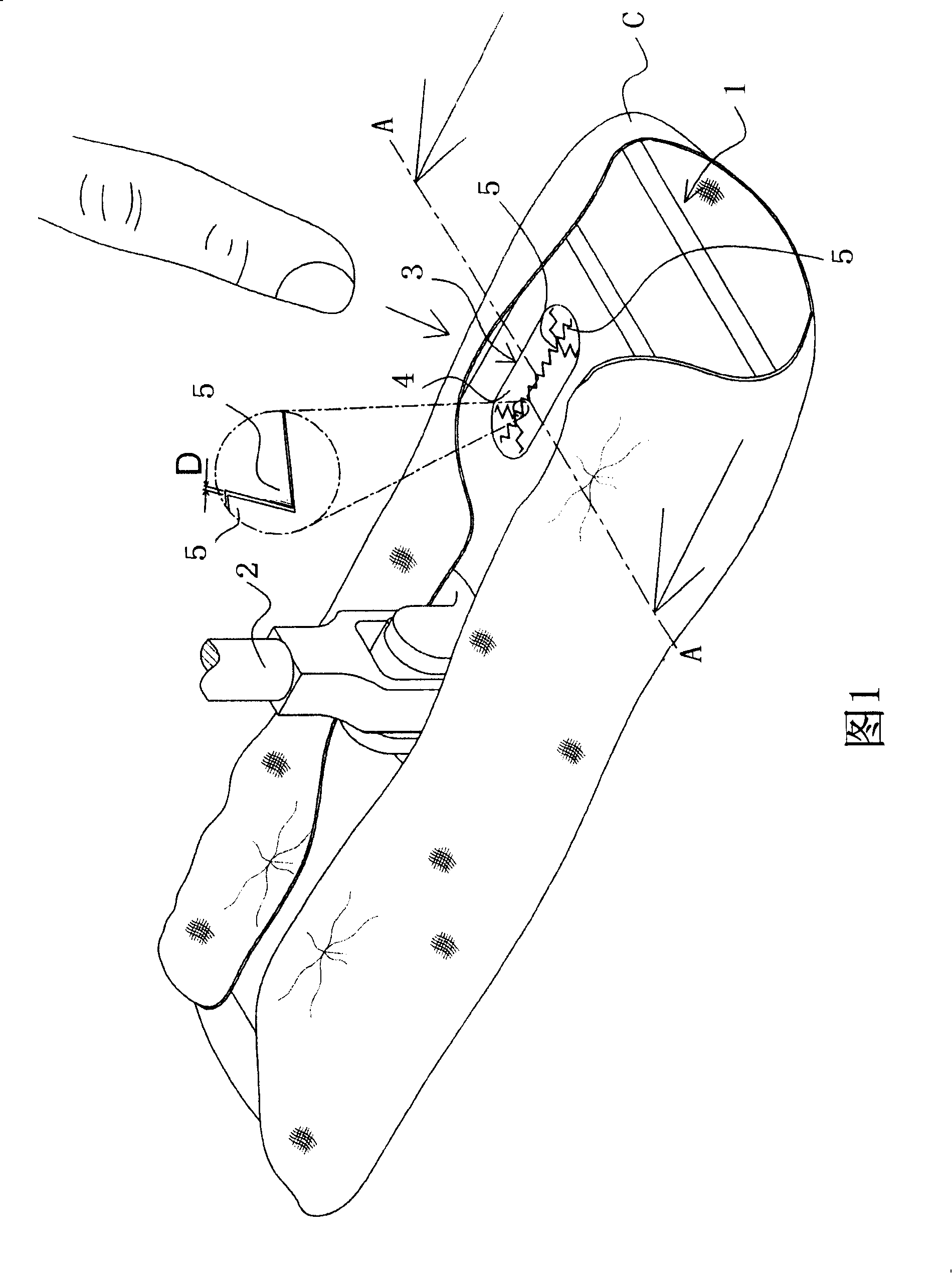
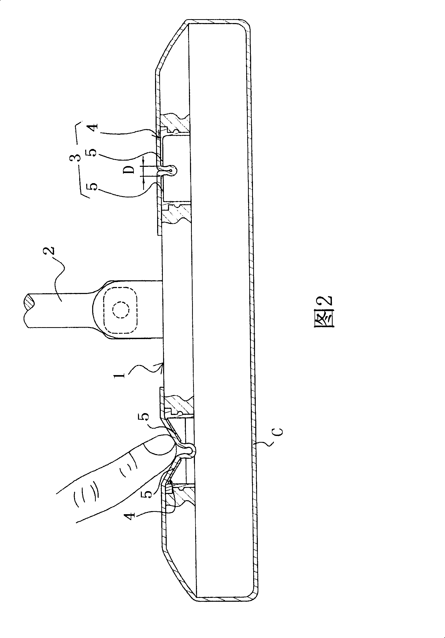
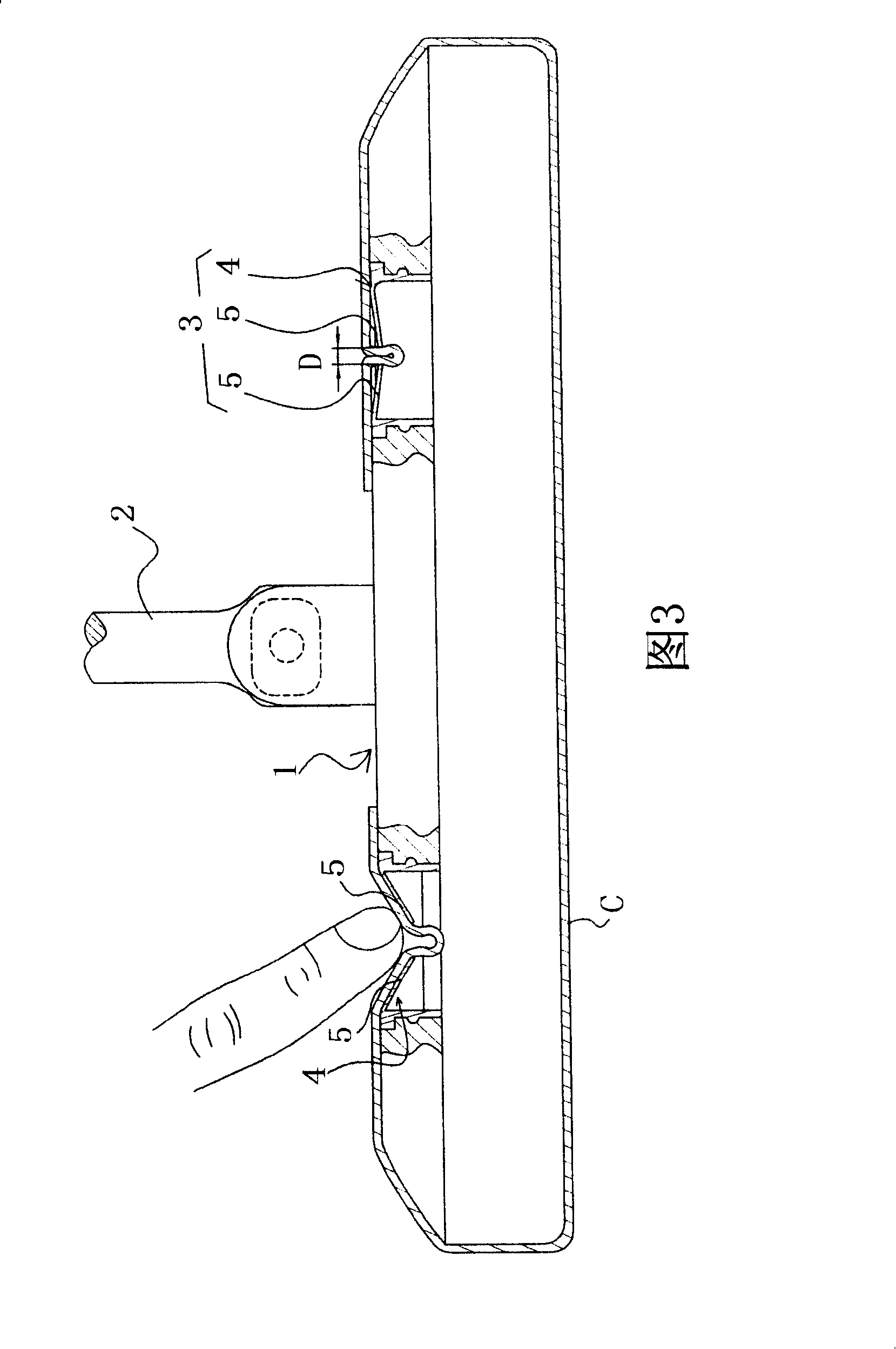
[0004] Although the mop cleaning cloth fixing structure described above can quickly and easily fix each end of the cleaning cloth C on the positioning part 3 of the base 1, however, in actual use, the strength of fixing the cleaning cloth C by the teeth part 5 is insufficient. , but cannot resist the frictional force produced between the cleaning cloth C and the ground, causing the cleaning cloth to break away from the positioning part 3, and easily pinch the user's fingers. When a plurality of tooth parts 5 are formed, they are formed by cutting or die punching, so that there is a gap D (as shown in Figure 1) around each tooth part 5. If the gap D is too large (larger than the cleaning cloth C twice the thickness), then the tooth part 5 does not fix the cleaning cloth C in a clamping manner, but only resets and closes the inner space to restrict the cleaning cloth C from exiting, without any clamping effect, if the gap D is larger hours (less than twice the thickness of the cleaning cloth C), the elastic force of the elastic sheet 4 cannot fully focus on the cleaning cloth C, resulting in insufficient clamping force applied to the cleaning cloth C by the tooth portion 5, which cannot be used for cleaning. The friction force generated by the cloth C and the ground is opposite

Method used


Image

  • Mop cleaning cloth fixing structure
  • Mop cleaning cloth fixing structure
  • Mop cleaning cloth fixing structure

Examples


Embodiment Construction

[0040] Relevant present invention is to reach above-mentioned purpose, the technical means that adopts and other effect, give a preferred embodiment now, and cooperate accompanying drawing to illustrate as follows.

[0041] The cleaning cloth of the present invention can be a rag, a dust removal cloth or an electrostatic dust removal paper, which will be described here first.

[0042] see Figure 4 to 8, Figure 4 It is the plan view of the fixed structure of mop cleaning cloth of the present invention; Fig. 5 is Figure 4 The cross-sectional schematic diagram of the B-B line of , showing that the cleaning cloth is not clamped in the clamping part; Figure 6 is Figure 4 Another schematic cross-sectional view of the B-B line of , showing that the clamping part clamps the cleaning cloth; Figure 7 is Figure 4 The C-C line sectional schematic diagram of , showing that the cleaning cloth does not enter the clamping part; and, Fig. 8 is Figure 4 The C-C line sectional schematic diag...


PUM


Abstract

The invention relates to a mop cleaning cloth fixed structure, the structure at least contains: a base, which is counter provided with a working bottom surface and a top part; and a plurality of positioning parts, which are respectively arranged at four angles of the top part at least, wherein, all the positioning parts are embedded on the base, the interior of the invention is hollow, the top end is provided with an elastic slice, a plurality of tooth parts are arranged on the slice to form a serrated opening, cleaning cloth is clamped in a staggered way, all the tooth parts respectively face to the interiors of the positioning parts to be extended with a clamping part, and the cleaning cloth is closely clamped by all the clamping parts to be fixed on the base.

Description

technical field [0001] The invention relates to a mop cleaning cloth fixing structure, in particular to a fixing structure for clamping and tightly fixing the cleaning cloth. Background technique [0002] The fixing structure of the current mop cleaning cloth can be roughly divided into two types: the buckle type and the clamping type. The more common clamping type fixing structure is widely available in the market because of its advantages of easy assembly and simple components. [0003] It is reported that today's clip-type dust mop mainly needs to include at least a base 1 and a handle 2 extending upward from the top of the base 1 (as shown in Figure 1); There are a plurality of positioning parts 3, which are used to fix each end of the cleaning cloth C so that it is tightly wrapped on the base 1. In more detail, the positioning parts 3 have an internal space (as shown in Figure 2 ), the top of the space is provided with an elastic sheet 4 that is flush with the top of t...

Claims


Application Information

Patent Timeline
Patent Type & Authority Applications(China)
IPC IPC(8): A47L13/46A47L13/20
Inventor 杨雅菁
Owner 杨雅箐
Learn More