
Method for rolling tube by hot-rolled seamless tube restraint core rod continuous rolling mill

A technology for restricting mandrels and seamless steel pipes, applied in metal rolling, metal rolling, rolls, etc., can solve the problems of difficult deformation of stainless steel, inability to separate from the mandrel, and holes on the surface, reaching a wide range of applications. Effect

Inactive Publication Date: 2008-07-02
BAOSHAN IRON & STEEL CO LTD
View PDF0 Cites 9 Cited by
  • Summary
  • Abstract
  • Description
  • Claims
  • Application Information

AI Technical Summary

Problems solved by technology

[0004] The current standard limited mandrel continuous rolling mill consists of five stands, the last three stands are basically round pass, the outer diameter of the bottom of the roll groove gradually decreases, and the last stand reaches the designed outer diameter of the waste pipe, the outer circumference of the pipe and the outer diameter of the roll. contact, the inner hole is kept in contact with the mandrel, and the pipe must be separated from the mandrel. After rolling out of the continuous rolling mill, it must overcome the resistance of the mandrel under the action of the front tube removal machine. This can be achieved in the production of carbon steel. However, in the production of stainless steel, due to the difficulty in deformation of stainless steel, the pipe cannot be separated from the mandrel under the action of the pipe remover, and holes are pulled out on the surface, and the pipe is stuck in the continuous rolling mill.

Method used


Image

  • Method for rolling tube by hot-rolled seamless tube restraint core rod continuous rolling mill
  • Method for rolling tube by hot-rolled seamless tube restraint core rod continuous rolling mill
  • Method for rolling tube by hot-rolled seamless tube restraint core rod continuous rolling mill

Examples


Embodiment

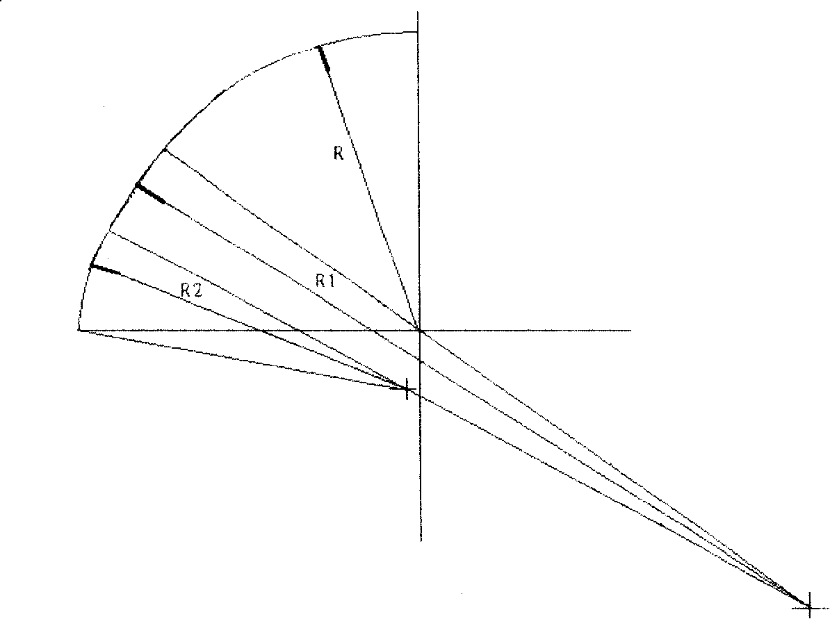
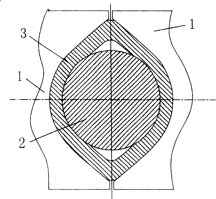
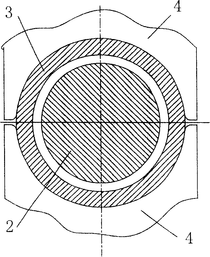
[0026] A method for rolling a hot-rolled seamless steel pipe with a limiting mandrel continuous rolling mill is to design a gap of 5mm between the pipe and the mandrel in the pass of the fifth roll, so that it is easy to remove the pipe; in order to generate the removal gap, the first The third and fourth racks adopt single-radius large side wall arcs to increase the ellipticity of the hole shape, and the side wall radii are 240 and 200 mm; the arc radius of the third to fifth racks' groove bottoms is 89 , 89 and 91.5mm, the value is from small to large, which is different from the original rule that the arc radius of the groove bottom is from large to small. The third and fourth frame groove bottom radii are smaller than the original hole type, but the side wall The radius increases more, and its circumference increases, so that there is enough circumference when entering the fifth frame, and there will be a gap for stripping after the circle is rounded.

[0027] The roll pas...


PUM


Abstract

The invention relates to a hot rolling continuous mill with seamless steel pipes and retained mandrels and a method of rolled pipes with the hot rolling continuous mill with seamless steel pipes and retained mandrels. The continuous mill comprises five mill rolls of a mill stand and mandrels and the mill roll consists of a hole; the continuous mill is characterized in that the hole pattern of a third mill roll and a fourth mill roll are in the shape of an oval while the fifth mill roll is in the shape of a perfect circle; the ovality of the pipe is gradually increased in the hole patterns of the third mill roll and the fourth mill roll and the circumference of the pipe is more than that of the perfect circle of the fifth mill roll so as to ensure that the pipe and the mandrel can form a clearance in a fifth mill stand and a pierced billet can be smoothly pulled out so as to separate the pipe and the mandrel. The invention ensures that the pipe and the mandrel can form the clearance in the fifth mill stand in the continuous mill with retained mandrels through the improvement of the hole pattern of the mill roll of the continuous mill and the pierced billet can be smoothly pulled out to separate the pipe and the mandrel, with no breakage of the pierced billet and no holes caused in the outer and inner surfaces. The invention can produce high-alloy steel pipes excluding stainless steel pipes and general carbon steel pipes and has a relatively wide scope of application.

Description

(1) Technical field [0001] The invention relates to a continuous rolling mill for a hot-rolled seamless steel pipe with a restraint mandrel. (2) Background technology [0002] The continuous rolling production process of hot-rolled seamless steel pipes has been developed from the full-floating mandrel continuous rolling in the 1980s to the current five-stand limited-movement continuous rolling process. Rolled in a rolling mill to achieve deformation and achieve the target outer diameter and wall thickness of the blank tube. Before the pipe enters the rolling mill, the mandrel is used as an internal deformation tool, its tail is clamped by the clamper, and it is sent into the inner hole of the pipe in advance, and enters the rolling mill together. The mandrel moves forward under the control of the clamper, and its movement speed is controlled. The outer circumference of the pipe is affected by the roll pass, the inner hole is affected by the mandrel, and the roll pass and th...

Claims


Application Information

Patent Timeline
IPC IPC(8): B21B17/04B21B27/02B21C45/00
Inventor 潘峰
Owner BAOSHAN IRON & STEEL CO LTD
Learn More