Method for forming part with hole

A molding method and part technology, applied in the field of parts molding, can solve problems such as increasing defective rate, affecting part forming quality, tearing, etc., and achieve the effect of reducing defective rate and improving forming quality

Inactive Publication Date: 2008-07-02
BYD CO LTD
View PDF0 Cites 32 Cited by
  • Summary
  • Abstract
  • Description
  • Claims
  • Application Information

AI Technical Summary

Problems solved by technology

Therefore, if figure 2 As shown, after the flanging is formed, the previously punched hole 2 will be deformed, o

Method used


Image

  • Method for forming part with hole
  • Method for forming part with hole
  • Method for forming part with hole

Examples


Embodiment Construction

[0014] Next, the method for forming a part with a hole provided by the present invention will be described in detail with reference to the accompanying drawings.

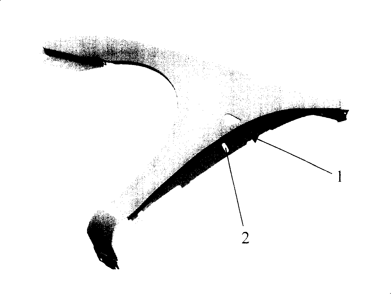
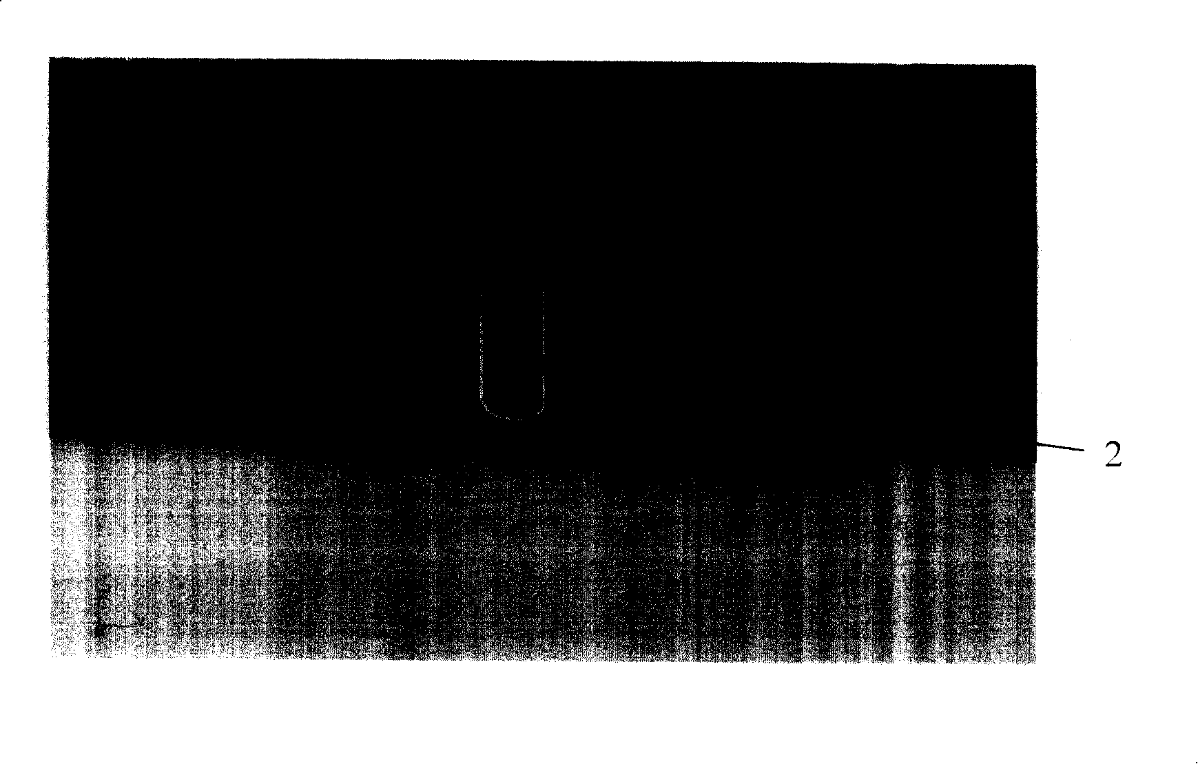
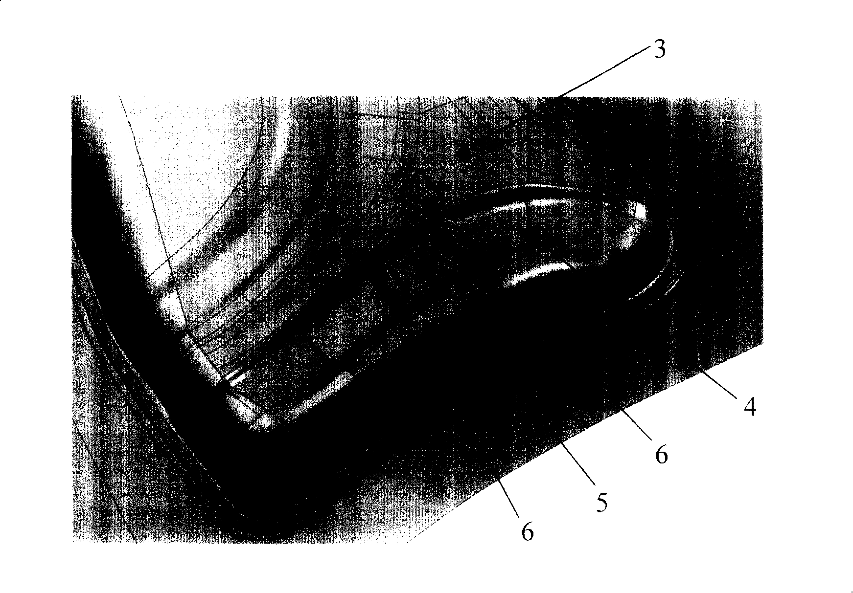
[0015] First, step a): drawing and shaping the sheet. Such as image 3 shown to form figure 1 The part shown is taken as an example. The drawn and shaped part includes a main body 3 and a joint edge 4 connected to the main body 3. The joint edge 4 includes a punching area 5 and a storage material located around the punching area 5. Tendon 6. The punching area 5 is used to form a hole, so the shape and size of the punching area 5 should be consistent with the shape and size of the hole to be formed. The storage ribs 6 are located around the punching area 5, so the location, arrangement and quantity of the storage ribs 6 should be determined according to the punching area 5, that is, the shape of the hole to be formed. For example, due to figure 1 The holes 2 on the part are oblong holes, so the punching area 5 i...


PUM


Abstract

The invention relates to a molding method of a part with a hole, comprising the following steps that: (a) a panel material is drawn and molded, the drawn and molded part comprises a body and a binding edge connected with the body, and the binding edge comprises a punching area and storing bars located around the punching area; (b) the punching area is punched; (c) the binding edge is flanged and shaped. As the storing bars are formed around the punching area through drawing and molding in the molding method of the part with a hole provided by the invention, the storing bar can balance the flowing of the material during the flanging and shaping process after punching the punching area, so as to compensate the needed material; therefore, the holes punched earlier do not deform, thus enhancing the molding quality of the parts and reducing the defective ratio.

Description

technical field [0001] The present invention relates to a method for forming parts, and more particularly, to a method for forming parts with holes. Background technique [0002] In recent years, the stamping process has been widely used in the automobile manufacturing industry. Many covering parts and interior panels in the vehicle are stamped by dies. However, some parts in the vehicle are more difficult to form because of their complex shape and structure. For example, some parts that have holes and must be punched before forming, such as figure 1 For the fender shown in , the joint side 1 that is combined with the side panel has a special shape of an inverse arc, and the joint side 1 has a hole 2 . [0003] Because the stamping process of this anti-arc structure is relatively complicated, it must be formed through two times of flanging, that is, it is first formed by vertical flanging, and then it is finally formed by side flanging using a wedge. Therefore, under the ...

Claims


Application Information

Patent Timeline
IPC IPC(8): B21D35/00B21D22/20B21D28/26B21D19/12B21D22/30
Inventor 黄河
Owner BYD CO LTD
Why Eureka
Try Eureka