Rotating device for casting base pad

A rotary, rotating shaft technology, applied in ingot workshop, foundry workshop, casting equipment, etc., can solve the problem of not being able to mass production, achieve the effect of uniform bottom pad, reduce production cost and improve efficiency

Inactive Publication Date: 2008-07-02
BENXI IRON & STEEL GROUP
View PDF0 Cites 4 Cited by
  • Summary
  • Abstract
  • Description
  • Claims
  • Application Information

AI Technical Summary

Problems solved by technology

[0003] The purpose of the present invention is to provide a rotary casting bottom pad device which solves the problem that the bottom pad cannot be mass-produced by directly casting the bottom pad with molten steel with electroslag steel surplus by utilizing the convenient centering of the ladle outlet and the bottom pad mold

Method used


Image

  • Rotating device for casting base pad

Examples


Embodiment Construction

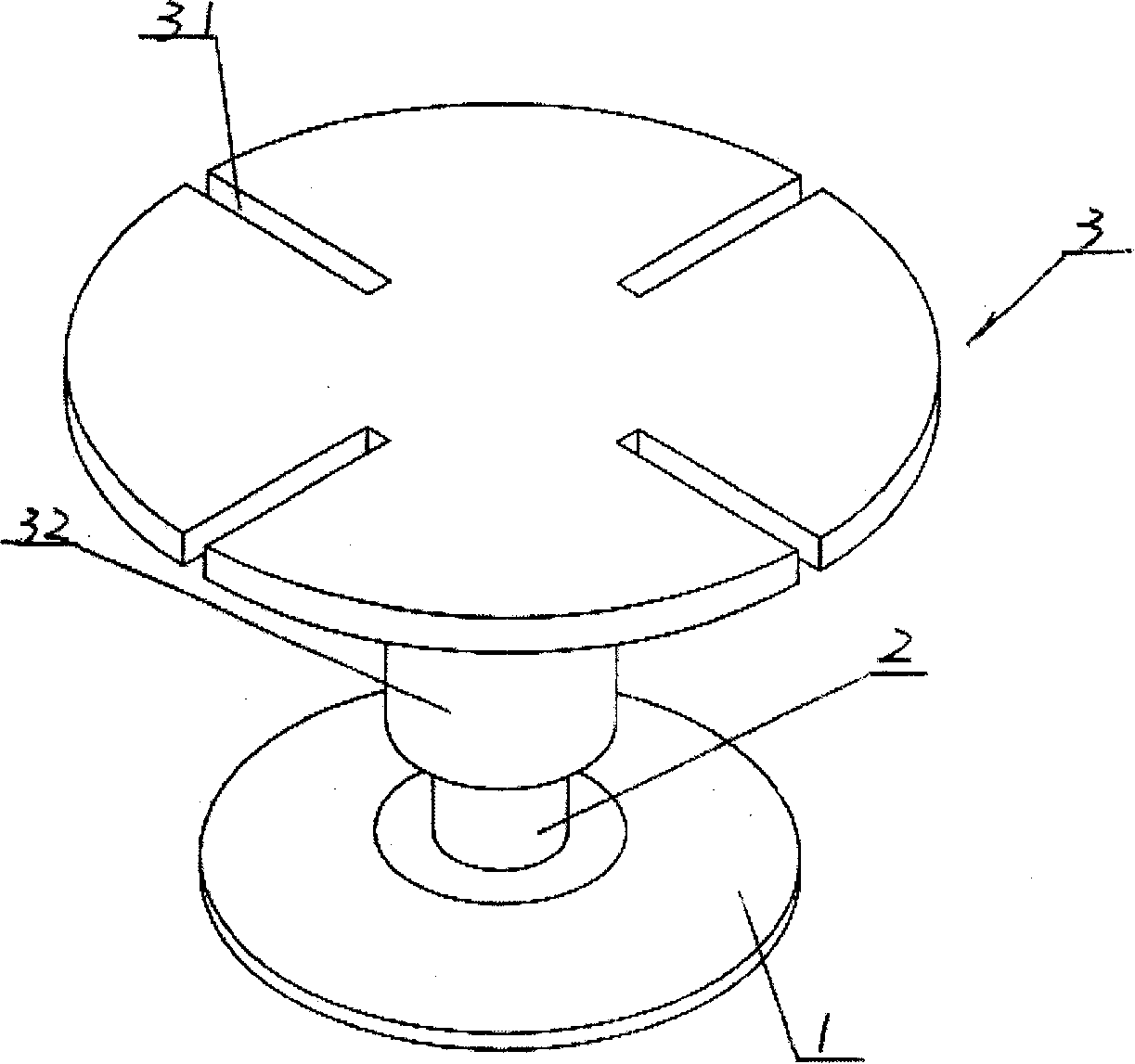
[0009] see figure 1 , which shows the overall structure of the appearance of an embodiment of the rotary casting base pad device proposed by the present invention. The device includes a base 1, a rotating shaft 2 installed in the middle area of ​​the base 1, and a support member installed on the top of the rotating shaft 2. The support member can be made of a disc-shaped part 3, four slots 31 for fixing the mold are arranged on two mutually perpendicular diameter directions of the disc-shaped part 3, and the length of each slot 31 is less than that of the disc-shaped part. The radius of piece 3. The bottom of the central part of the disc-shaped part 3 is provided with a socket 32, and the end of the disc-shaped part 3 is connected with the end of the rotating shaft 2 through the plug-in sleeve 32. When the rotating shaft 2 rotates, the disc-shaped part 3 can be driven to rotate. .

[0010] When in use, the mold is placed on the upper surface of the disc-shaped part 3, and t...


PUM


Abstract

The invention relates to a rotary bottom mat casting device which comprises a rotation axis restricted by a base and a bracing member used for fixing a mould and installed on the top of the rotation axis. By continuously rotating a bottom mat mould to realize continuous casting of the bottom mat, but the bottom mat module is unnecessary to be aligned with an opening of a ladel; therefore, by adopting the device, continuous casting of multi bottom mats with the same furnace of molten steel can be realized, efficiency can be improved, and the production cost can be reduced.

Description

Technical field: [0001] The invention relates to a casting device for a bottom pad used in producing electroslag steel by using an electroslag remelting furnace, in particular to a rotary casting bottom pad device. Background technique: [0002] The bottom pad is one of the raw materials required to produce bearing steel, that is, electroslag steel, by electroslag remelting method, and its quality is directly related to the quality of electroslag steel. In the prior art, the sources of the bottom pad mainly include the following four aspects: one is to replace it with ordinary steel plates. Although this alternative method is low in cost and rich in material sources, due to the relatively large amount of impurities in ordinary steel plates, The steel produced with it will have quality problems, and is not suitable for the production of high-purity steel; the second is to use the leftover material of electroslag steel and make the bottom pad through forging and other processe...

Claims


Application Information

Patent Timeline
Patent Type & Authority Applications(China)
IPC IPC(8): B22D9/00B22D45/00
Inventor 王恒张万发陈学权梁启华
Owner BENXI IRON & STEEL GROUP
Why Eureka
Try Eureka