
Fast copper bar cut-off machine

A cutting machine and bar cutting machine technology, which is applied to metal sawing equipment, sawing machine devices, metal processing equipment, etc., can solve the problems of material waste and uneven cutting surface of metal bars, save raw materials, improve efficiency, and improve utilization rate. Effect

Inactive Publication Date: 2008-07-02
东莞市瑞为电器配件有限公司
View PDF0 Cites 13 Cited by
  • Summary
  • Abstract
  • Description
  • Claims
  • Application Information

AI Technical Summary

Problems solved by technology

[0003] In order to overcome the technical deficiencies of the existing uneven cut surface of metal rods and waste of materials; the purpose of the present invention is to provide a fast copper rod cutting machine that rotates the metal rod after being clamped, and then saws the disc to cut

Method used


Image

  • Fast copper bar cut-off machine

Examples


Embodiment

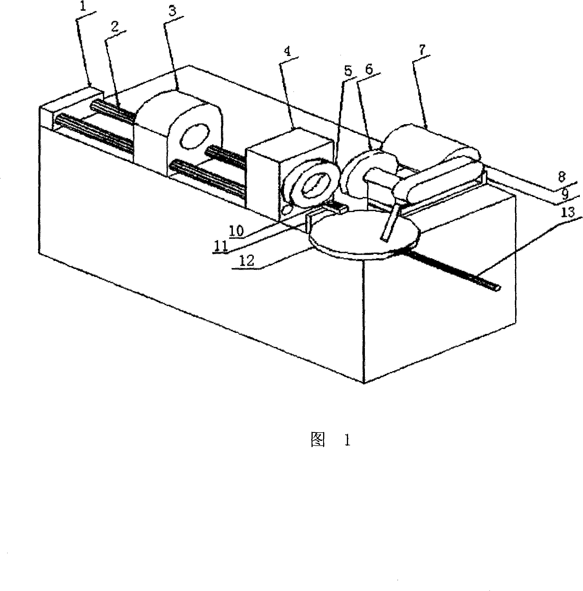
[0017] Embodiment: Referring to FIG. 1 , a fast copper rod cutting machine provided by the present invention includes a base on which a chuck 5 fixing seat, that is, a spindle box 4 and a sawing motor 7 are provided. A rotating motor and a driving gear set are arranged in the base. The outside of the main shaft box 4 is provided with a collet 5, which is fixedly connected with the rotating shaft in the main shaft case 4, and the belt pulley of the rotating shaft is connected with the drive gear group through a belt; Two parallel guide posts 2 are arranged on the top, and the spindle box 4 is arranged at one end of the guide posts 2 . A pipe slider 3 is arranged on the guide post 2 . A pipe hole is provided on the pipe slider 3, and the central axis of the pipe hole overlaps with the axis of the rotating shaft. Pipe slider 3 is used to support the other end of the metal rod. While spinning, the other end of the metal rod rests in the tube hole.

[0018] A saw motor slide bl...


PUM


Abstract

The invention discloses a fast copper rod cutting machine, comprising a base which is provided with a chuck fixed seat and a slitting disc motor seat. The invention is characterized in that the chuck fixed seat is a mainshaft box which is provided with a chuck which is fixedly connected with a rotary shaft in the mainshaft box; the invention is also provided with a rotary motor and a driving gear group; the rotary shaft is connected with the driving gear group; the rotary axis line of the slitting disc in the slitting disc motor seat is parallel to the rotary shaft. The invention has the advantages of improving the cutting efficiency more than 10 times, improving the utilization ratio of the saw bit, saving the cost, smoothening the end surface in the cutting process, saving raw material, and improving the efficiency of post-process in disguised form.

Description

technical field [0001] The invention relates to a metal cutting machine, in particular to a fast copper rod cutting machine. Background technique [0002] Existing metal rods all adopt saw disc cutting more. The cutting principle is: the bar is fixed and clamped for cutting. Such cutting efficiency is low (if the bar is 100mm, it must be cut by 100mm). The saw blade has a large cutting distance and high pressure during the cutting process, which causes the saw blade to be damaged quickly. It is easy to cause the end face to be inclined during the cutting process, which must be cut off during production, wasting raw materials. There is no good solution for this yet. Invention content: [0003] In order to overcome the technical deficiencies of the existing uneven cut surface of metal rods and waste of materials; the purpose of the present invention is to provide a fast copper rod cutting machine that rotates the metal rod after being clamped, and then cuts it with a saw...

Claims


Application Information

Patent Timeline
Patent Type & Authority Applications(China)
IPC IPC(8): B23D47/06
Inventor 张瑞廷
Owner 东莞市瑞为电器配件有限公司
Learn More