Washing machine deceleration clutch, washing machine and washing mode thereof

A technology of deceleration clutch and washing machine, applied in the field of washing machine, can solve the problems of simple water flow and failure to achieve washing effect, etc., and achieve the effects of high washing efficiency, saving washing time and improving washing rate

Active Publication Date: 2010-12-29
NINGGUO JULONG IND
View PDF4 Cites 0 Cited by
  • Summary
  • Abstract
  • Description
  • Claims
  • Application Information

AI Technical Summary

Problems solved by technology

[0002] In my country's patent literature, there is a patent document with an application number of 02116376.6 called a fully automatic deceleration clutch. The above deceleration clutch is mainly composed of an input shaft, an input shaft sleeve, an output shaft, an output shaft sleeve, a brake wheel, The deceleration mechanism inside the brake wheel and the clutch parts installed on the input shaft sleeve are composed. The deceleration mechanism is planetary gear transmission. This washing machine deceleration clutch is used on the pulsator washing machine. When the washing machine is washing, the pulsator performs bidirectional reciprocating rotation , the inner bucket performs a two-way reciprocating rotation opposite to that of the pulsator, but the water flow is still relatively simple, and the ideal washing effect has not been achieved.

Method used


Image

  • Washing machine deceleration clutch, washing machine and washing mode thereof
  • Washing machine deceleration clutch, washing machine and washing mode thereof
  • Washing machine deceleration clutch, washing machine and washing mode thereof

Examples


Embodiment Construction

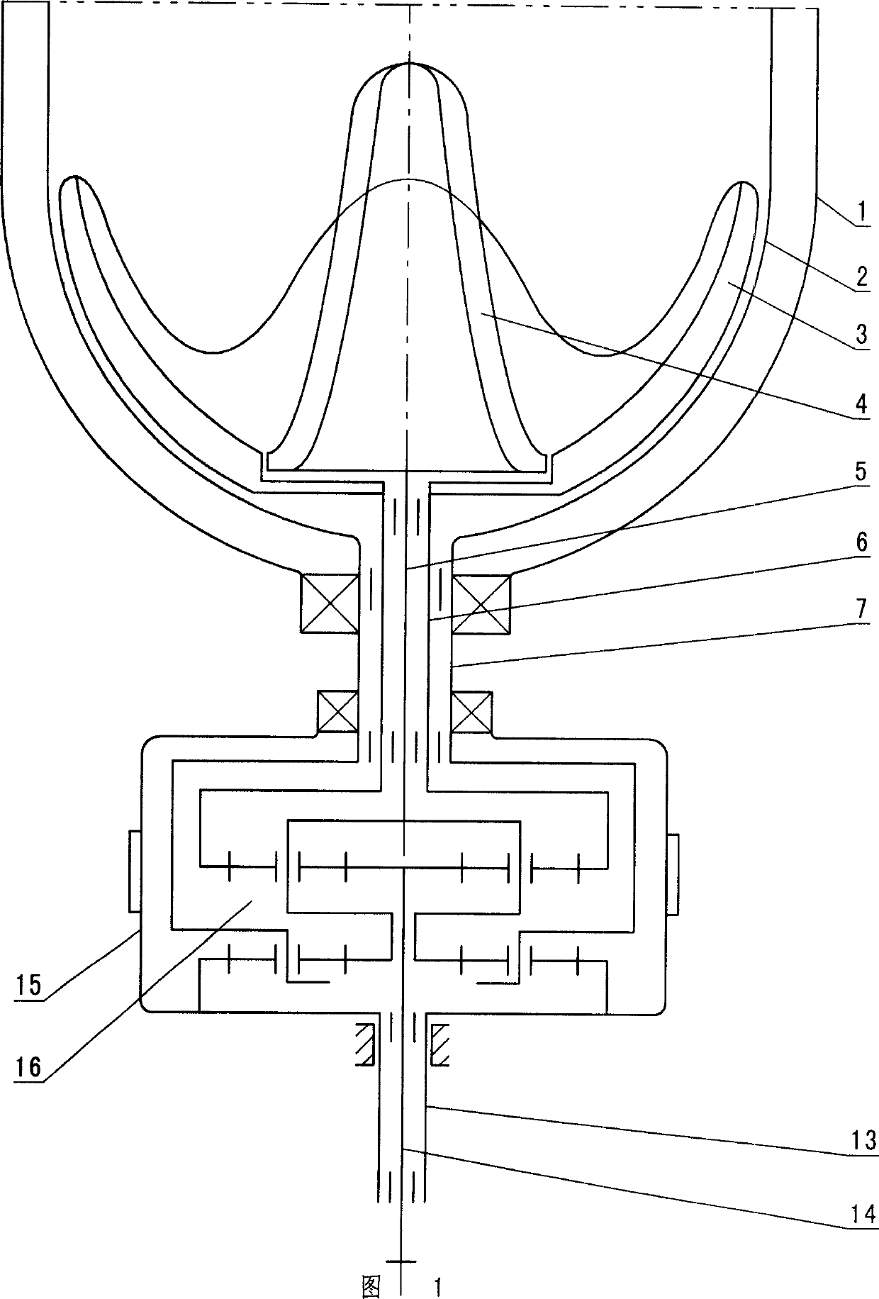
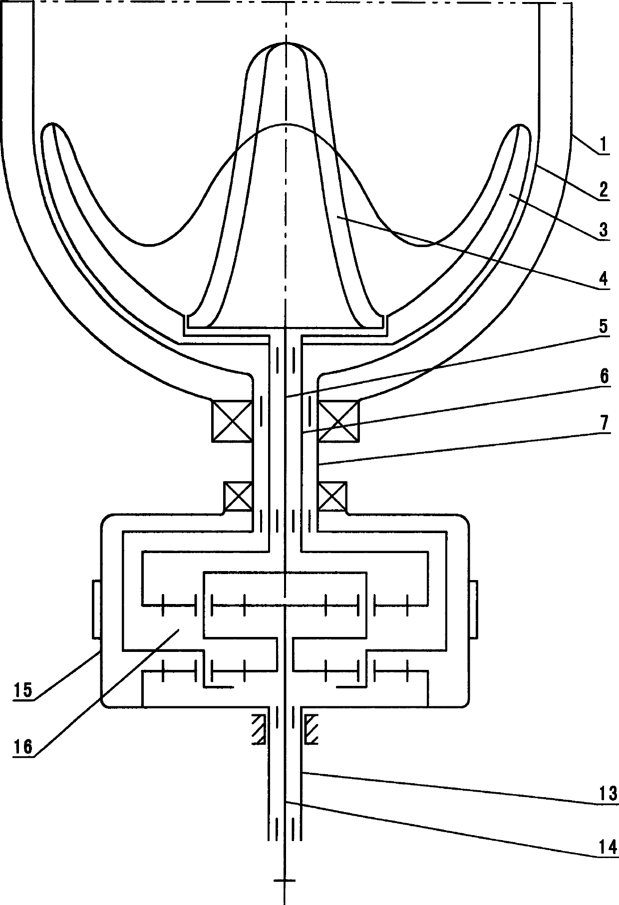
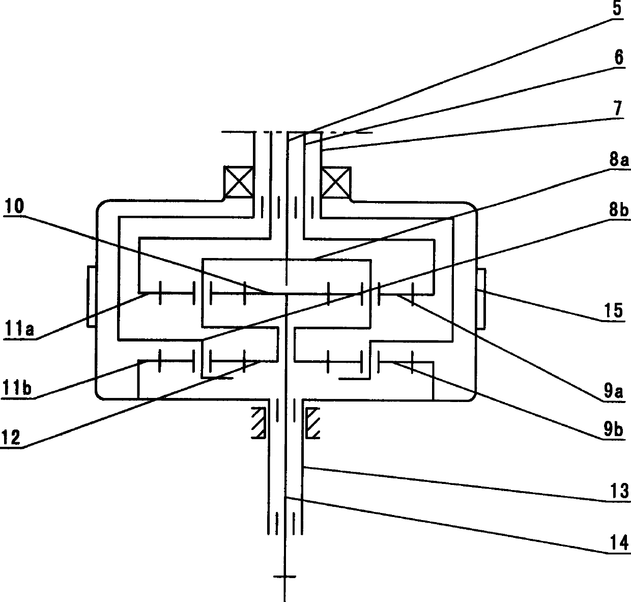
[0022] combine figure 1 , a washing machine deceleration clutch, mainly composed of an input shaft 14, an input shaft sleeve 13, a deceleration mechanism 16, a brake wheel 15, a small wave wheel shaft 5, a large wave wheel shaft sleeve 6 and an inner barrel shaft 7, and the input shaft 14 is supported on the input shaft sleeve 13 Inside, the reduction mechanism 16 is respectively connected with the small wave wheel shaft 5, the large wave wheel shaft sleeve 6 and the inner barrel shaft 7, the brake wheel 15 is connected with the input shaft sleeve 13, and the speed reduction mechanism 16 is placed inside the brake wheel 15; the small wave wheel shaft 5, The three output shafts of the large wave wheel shaft sleeve 6 and the inner barrel shaft 7 are concentrically fitted, the small wave wheel shaft 5 is supported in the large wave wheel shaft sleeve 6, and its upper and lower ends are respectively connected with the small wave wheel 3 and the reduction mechanism 16, and the large...


PUM


Abstract

A decelerating clutch of a washer and the washer and a washing mode thereof relates to the technical field of washer. An output shaft of the decelerating clutch includes a small wave wheel shaft, a large wave wheel shaft and an inner barrel shaft, wherein the small wave wheel shaft is supported in the large wave wheel shaft, and the large wave wheel shaft is supported in the inner barrel shaft. By adopting the deceleration mechanism of the decelerating clutch, the invention can simultaneously drive a large wave wheel, a small wave wheel and an inner barrel to rotate. A washer manufactured by using the decelerating clutch comprises a small wave wheel and a large wave wheel, wherein the small wave wheel is fixedly arranged on the small wave wheel shaft and positioned at the middle portion of the large wave wheel; the large wave wheel is fixedly arranged on the large wave wheel shaft; and the inner barrel is fixedly arranged on the inner barrel shaft. The washer manufactured by using thedecelerating clutch is operated in such a mode that the small wave wheel, the large wave wheel and the inner barrel make reciprocating rotation in mutually reverse directions at different speeds and different rotation angles by a ratio in two directions to produce complex and crossing shock water flow to scrub and clean the clothes, thus completely rotating the clothes, achieving strong scrubbingforce and improving the cleaning rate.

Description

technical field [0001] The technical solution of the invention relates to the technical field of washing machines, in particular to the automatic optimization design of the washing machine and its deceleration clutch, and also to the washing method of the washing machine. Background technique [0002] In my country's patent literature, there is a patent document with an application number of 02116376.6 called a fully automatic deceleration clutch. The above deceleration clutch is mainly composed of an input shaft, an input shaft sleeve, an output shaft, an output shaft sleeve, a brake wheel, The deceleration mechanism inside the brake wheel and the clutch parts installed on the input shaft sleeve are composed. The deceleration mechanism is planetary gear transmission. This washing machine deceleration clutch is used on the pulsator washing machine. When the washing machine is washing, the pulsator performs bidirectional reciprocating rotation , the inner barrel performs a two-...

Claims


Application Information

Patent Timeline
Patent Type & Authority Patents(China)
IPC IPC(8): D06F37/40D06F17/08D06F39/00F16H1/28
Inventor 潘雪珍
Owner NINGGUO JULONG IND
Why Eureka
Try Eureka