Rotating switch

A technology of rotary switch and switch frame, which is applied to electric switches, the arrangement of accessories on instrument panels, electrical components, etc., can solve the problem of not getting knocking feeling, and achieve assembly man-hours, improve angular accuracy, and fit strength. unifying effect

Inactive Publication Date: 2008-07-02
SHINMEI MOTOR
View PDF1 Cites 16 Cited by
  • Summary
  • Abstract
  • Description
  • Claims
  • Application Information

AI Technical Summary

Problems solved by technology

Therefore, when the rotary operation knob 203 is rotated, the plate springs 215, 216

Method used


Image

  • Rotating switch
  • Rotating switch
  • Rotating switch

Examples


Embodiment Construction

[0040] Hereinafter, embodiments of the present invention will be described in detail according to the accompanying drawings.

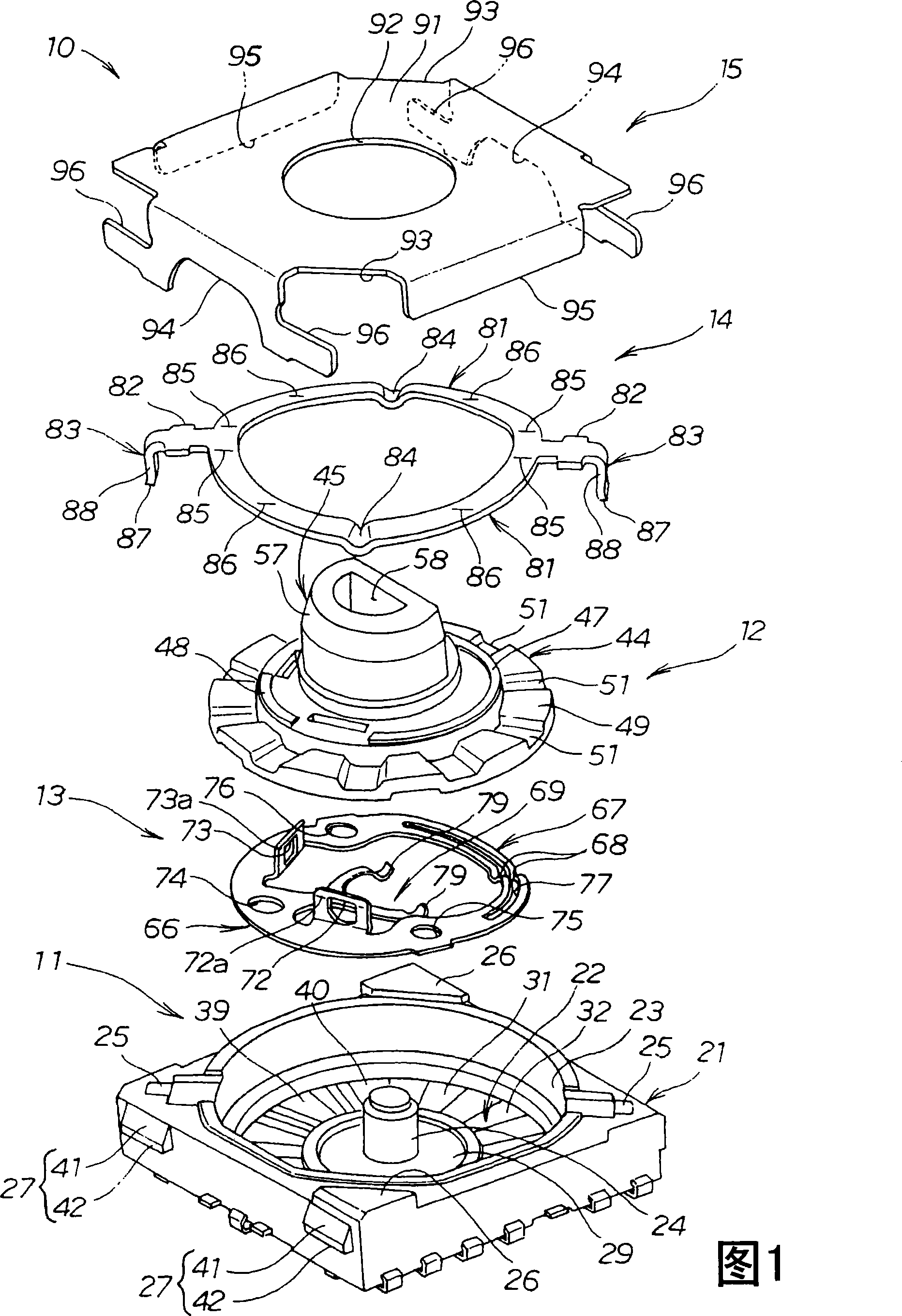
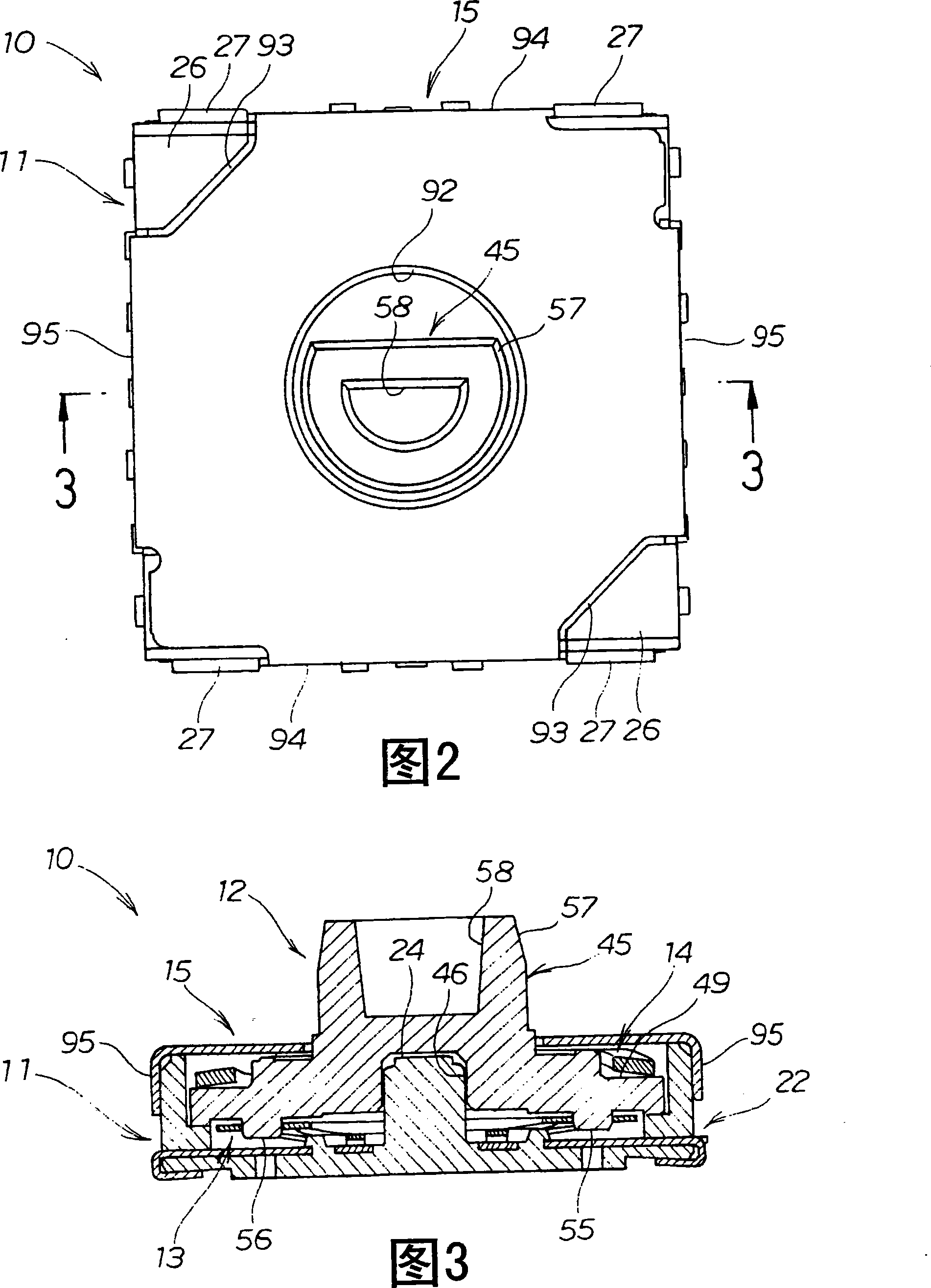
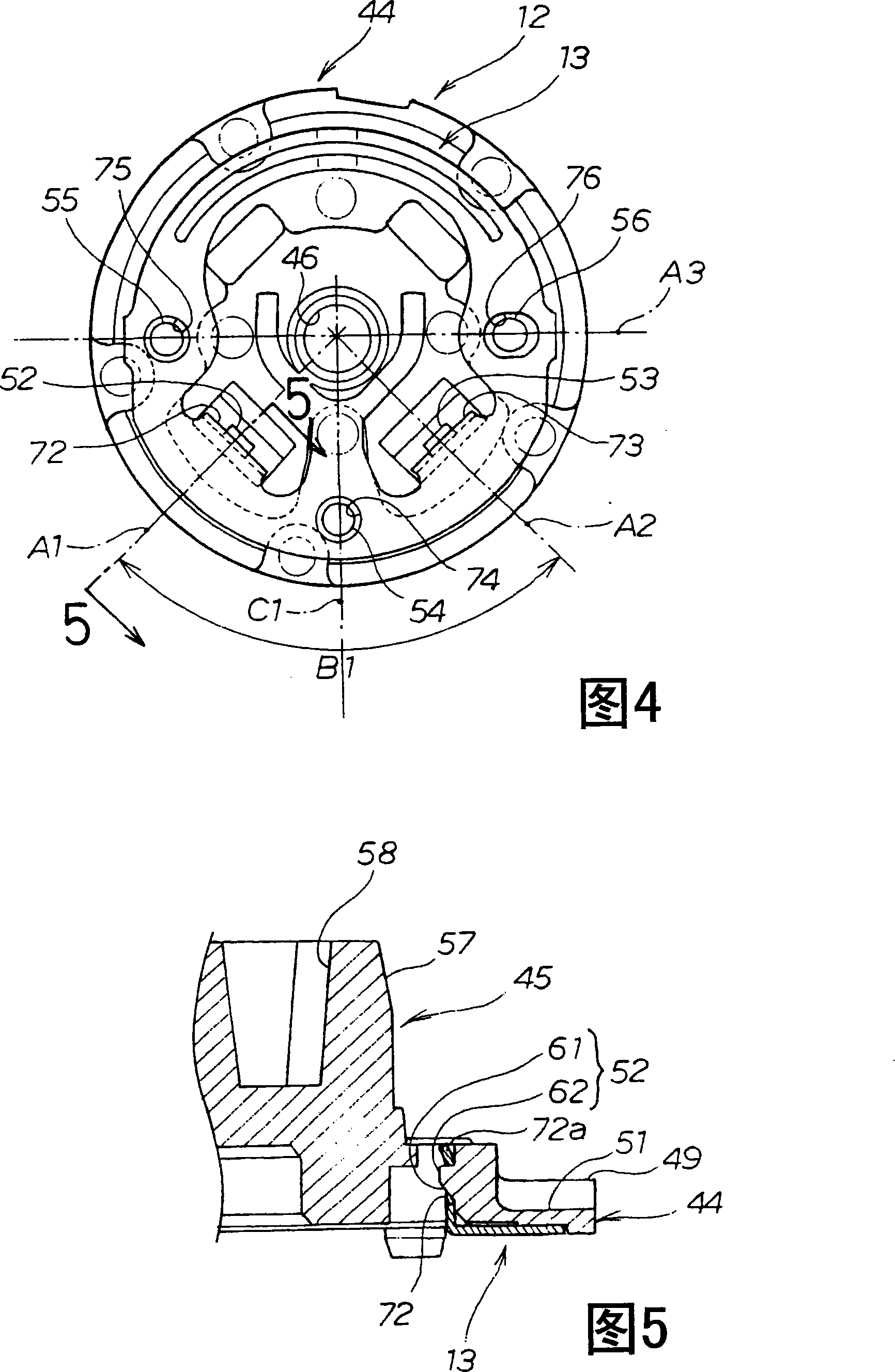
[0041] As shown in Fig. 1, Fig. 2 and Fig. 3, the rotary switch 10 is composed of the following components: a substantially square switch frame 11; a rotary operation knob 12 rotatably installed on the switch frame 11; The contact piece 13 on 12; the leaf spring 14 engaged on the switch frame 11; the cover 15 covering the switch frame 11.

[0042]The switch frame 11 is made up of the following parts: a frame body 21 made of insulating material; a fixed contact 22 provided on the frame body 21; in order to expose the sliding part of the fixed contact 22 of the contact piece 13 sliding, the frame body The receiving recess 23 provided on 21; the cylindrical support shaft 24 provided in the approximate center of the receiving recess 23; the engaging parts (press-fit grooves) 25, 25 provided on the two opposite corners of the frame main body 21; The two en...


PUM


Abstract

The present invention discloses a rotary switch (10) for coverring a lid (15) on a switch rack (11) containing permanent joint (22). Embedding contact piece (13) contacting to the permanent joint on a rotary operating knob (12), after accepting the contact piece and the rotary operating knob as well as a leaf spring (14) on the switch rack together in order, covering the lid (15) on the switch rack (11) and assembling the rotary switch. The rotary switch uses the switch rack, the contact piece, the rotary operating knob, the leaf spring and the lid as composing component. The rotary switch implements simplification of constitution thereof and miniaturization with low cost, also obtains measurable knocking sense and excellent operating sense.

Description

technical field [0001] The present invention relates to a rotary switch, which is used for mode setting of a digital camera, etc., and particularly relates to a rotary switch which switches contact points by contacting a contact piece with a plurality of fixed contacts and rotating. Background technique [0002] At present, a plurality of fixed contacts are provided on the switch frame (switch base), and the rotary operation knob (rotary plate) used as a switch switch is rotatably installed on the above-mentioned switch frame, and the contact piece (rotor) is installed on the rotary operation knob. , so that the contact piece is in contact with the fixed contact of the switch frame, such a rotary switch is known. [0003] Such a rotary switch has a structure in which recesses are provided at predetermined intervals on the outer periphery of the rotary operation knob, and a ratchet mechanism such as a leaf spring is provided in the recesses. [0004] For example, in Japanese...

Claims


Application Information

Patent Timeline
IPC IPC(8): H01H19/10H01H19/20H01H19/04
CPCB60K37/06B60K2350/102B60K2370/126
Inventor 山本均
Owner SHINMEI MOTOR
Why Eureka
Try Eureka