IC chip inner capacitor discharging control circuit

A discharge control and integrated circuit technology, applied in the direction of circuits, electric solid devices, electrical components, etc., can solve the problem of increasing static power consumption of chips, achieve simple and reliable data timing, avoid static power consumption, and improve work efficiency.

Inactive Publication Date: 2008-07-02
SHANGHAI BEILING
View PDF0 Cites 0 Cited by
  • Summary
  • Abstract
  • Description
  • Claims
  • Application Information

AI Technical Summary

Problems solved by technology

[0007] In this way, in the usual design, it is hoped that there is a relatively large internal capacitor to provide energy for the chip to ensure the reliability of the t1 time, and it is also hoped that the internal capacitor is smaller to ensure the reliability of the t2 time. Therefore, the general design allows the chip to always maintain a DC path. To maintain the discharge of the internal capacitance of the chip during the period from t1 to t2, which increases the static power consumption of the chip

Method used


Image

  • IC chip inner capacitor discharging control circuit
  • IC chip inner capacitor discharging control circuit

Examples


Embodiment Construction

[0019] Preferred embodiments of the present invention will be described in detail below in conjunction with the accompanying drawings.

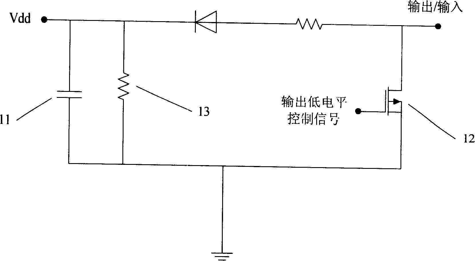
[0020] figure 1 It is a structural diagram of a capacitor discharge control circuit in a common integrated circuit chip. As shown in the figure, after a signal is input to the chip, the capacitor 11 is charged, and the voltage on it becomes the internal power supply Vdd of the chip. Resistor 13 plays the role of forming a direct current path to maintain uA level quiescent current.

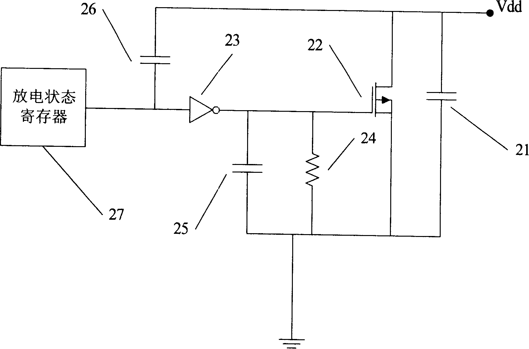
[0021] figure 2 It is a structural diagram of a capacitor discharge control circuit in an integrated circuit chip in a preferred embodiment of the present invention.

[0022] As shown in the figure, the circuit of this embodiment removes figure 1 The resistor 13 between the power supply and the ground in the circuit cancels this DC path and the static DC power consumption it produces.

[0023] The MOS tube 22 is a discharge tube for directly discharging the ...


PUM


Abstract

The invention relates to a discharging and control circuit of a capacitor in an integrated circuit chip, which comprises a capacitor as an inner power of the chip and an MOS tube parallel connected with the capacitor. The discharging and control circuit also comprises the following processes: a discharging status register used for controlling the discharging status of the capacitor; a reverser connected between the discharging status register and the grid of the MOS tube, which is used for controlling the open and close of the MOS tube so as to discharge to the capacitor; a resistance used for discharging to the grid of the MOS tube and to the capacitor connected with the grid of the MOS tube, one end of the resistance is connected with ground, while another end is connected with the grid of the MOS tube. The discharging and control circuit of the capacitor in the integrated circuit chip provided by the invention effectively ensures simple and reliable performance of the data time sequence, meanwhile avoids the static power consumption of the integrated circuit chip, increases nicely the working efficiency of the integrated circuit chip.

Description

technical field [0001] The invention relates to a discharge control circuit, in particular to a circuit for controlling the discharge of a capacitor in an integrated circuit chip, which is suitable for integrated circuit chips such as single-wire transmission protocols. Background technique [0002] The integrated circuit chip may not be provided with a special power input terminal, but the capacitor in the chip may be charged by inputting a high level signal to any other port or ports of the chip. When the port is at a low level, only The normal function of the chip is maintained by discharging the capacitor in the chip. [0003] The above situation is equivalent to multiplexing the data port as the power input port. For the convenience of illustration, it is assumed that there is only one such port (because if there are multiple such ports, any one of them will charge the capacitor in the chip when it is high), and when the port is low, the capacitor will be fully used. ...

Claims


Application Information

Patent Timeline
Patent Type & Authority Applications(China)
IPC IPC(8): H01L27/00H01L27/02H03K17/687
Inventor 庄宇罗鹏
Owner SHANGHAI BEILING
Why Eureka
Try Eureka